


MANUAL HANDBOOK
Automatic thickness controller for sawing frame machines
Automatic thickness controller ISP
machine.
Before assembly and start please read this handbook manual carefully, instructions
provided help you in correct mounting and operating of our product.
MANUAL HANDBOOK
Automatic thickness controller for sawing frame machines
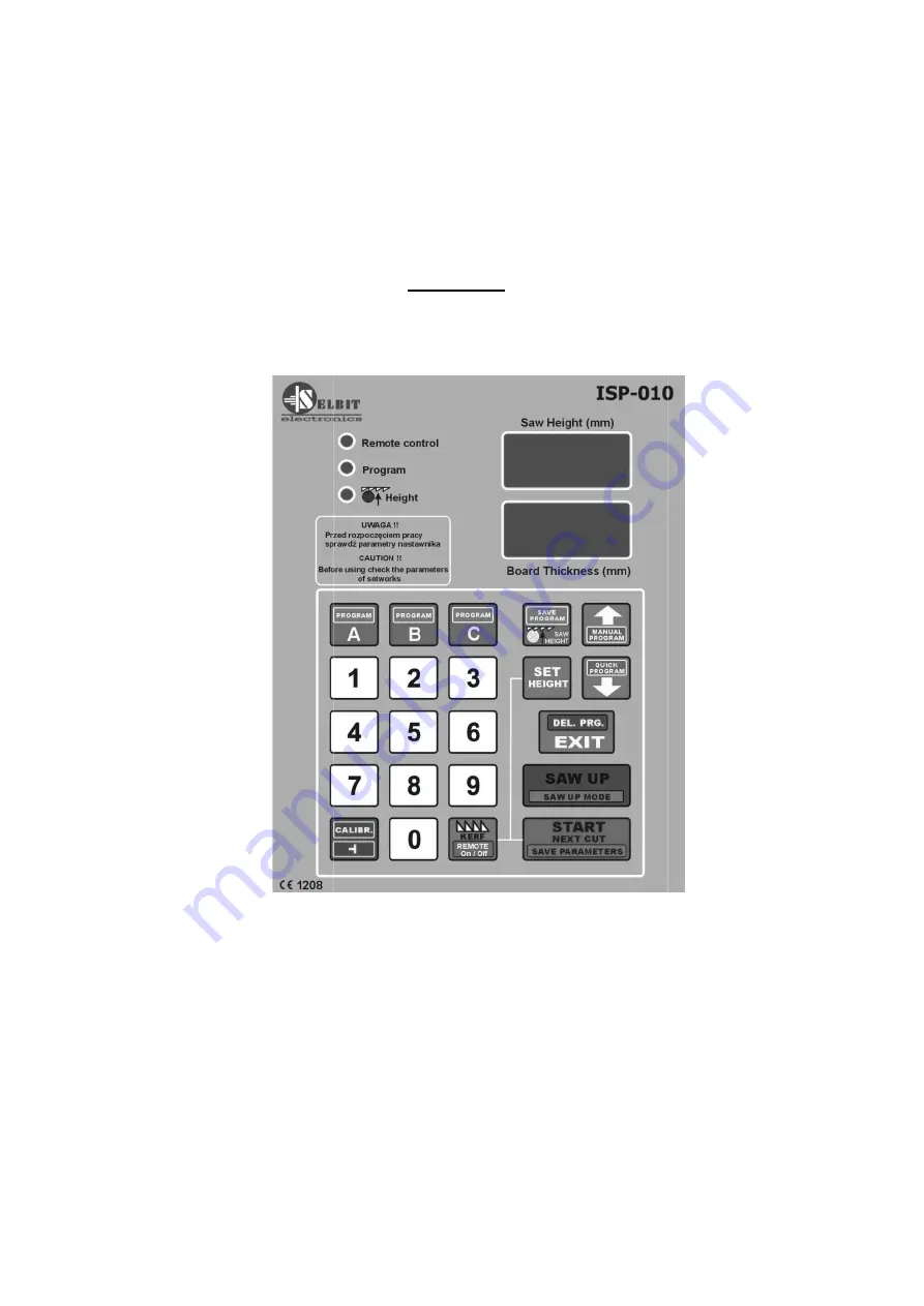
ISP - 010
Automatic thickness controller ISP-010 is designed to be mounted on the sawing frame
Before assembly and start please read this handbook manual carefully, instructions
provided help you in correct mounting and operating of our product.
Automatic thickness controller for sawing frame machines
010 is designed to be mounted on the sawing frame
Before assembly and start please read this handbook manual carefully, instructions
Summary of Contents for ISP - 010
Page 17: ...www selbit pl 17...
Page 19: ...www selbit pl 19...


