background image

U.3.14

SEL-421 Relay

User’s Guide

Date Code 20090715

PC Software

Expression Builder

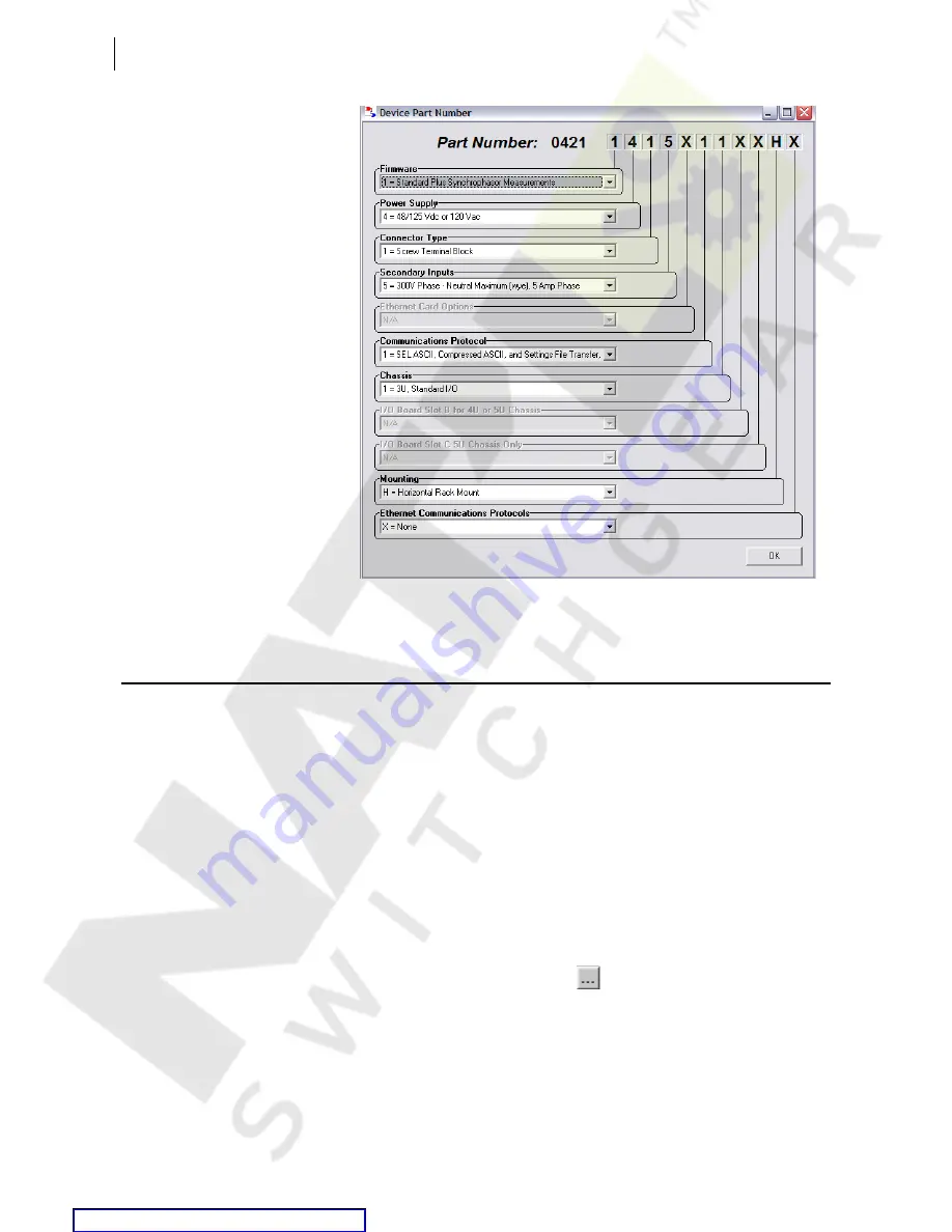
Figure 3.16

Setting the Relay Part Number in 

AC

SEL

ERATOR

 QuickSet

Expression Builder

SEL

OGIC

 control equations are a powerful means for customizing relay 

performance. Creating these equations can be difficult because of the large 
number of relay elements (Relay Word bits) and analog quantities in the relay.

AC

SEL

ERATOR

 QuickSet simplifies this process with the 

Expression Builder

a rules-based editor for programming SEL

OGIC

 control equations. The 

Expression Builder

 organizes relay elements, analog quantities, and 

SEL

OGIC

 control equation variables and focuses your equation decision-

making. The 

Expression Builder 

checks basic rules and flags mistakes in 

SEL

OGIC

 control equation settings.

Access the 
Expression Builder

Settings dialog boxes (see 

Figure 3.17

) in the 

Relay Editor

 window show the 

following (ellipsis) button:


Click this button of a SEL

OGIC

 equation to use the 

Expression Builder

.

Courtesy of NationalSwitchgear.com

Summary of Contents for 421

Page 1: ...20090715 SEL 421 Relay Protection and Automation System Instruction Manual User s Guide PM421 01 NB Courtesy of NationalSwitchgear com ...

Page 2: ...ineering Laboratories Inc reserves all rights and benefits afforded under federal and international copyright and patent laws in its products including without limitation software firmware and documentation The information in this manual is provided for informational use only and is subject to change without notice Schweitzer Engineering Laboratories Inc has approved only the English language manu...

Page 3: ...e Relay Settings U 3 9 Expression Builder U 3 14 Analyze Events U 3 16 HMI Meter and Control U 3 21 Section 4 Basic Relay Operations Inspecting a New Relay U 4 1 Connecting and Applying Power U 4 3 Establishing Communication U 4 4 Changing the Default Passwords U 4 6 Checking Relay Status U 4 10 Making Simple Settings Changes U 4 13 Examining Metering Quantities U 4 33 Reading Oscillograms Event R...

Page 4: ...it Breaker Failure Application Examples A 1 148 Section 2 Monitoring and Metering Circuit Breaker Monitor A 2 1 Station DC Battery System Monitor A 2 21 Metering A 2 26 Section 3 Analyzing Data Data Processing A 3 2 Triggering Data Captures and Event Reports A 3 4 Duration of Data Captures and Event Reports A 3 5 Oscillography A 3 7 Event Reports Event Summaries and Event Histories A 3 11 SER Sequ...

Page 5: ...munications Assisted Tripping Logic R 1 87 Directional Comparison Blocking Scheme R 1 88 Permissive Overreaching Transfer Tripping Scheme R 1 91 Directional Comparison Unblocking Scheme Logic R 1 100 Trip Logic R 1 105 Circuit Breaker Failure Protection R 1 115 Section 2 Auto Reclosing and Synchronism Check Auto Reclosing R 2 2 One Circuit Breaker Auto Reclosing R 2 4 Two Circuit Breaker Auto Recl...

Page 6: ...or Synchrophasors R 7 9 Synchrophasor Relay Word Bits R 7 19 Synchrophasor Analog Quantities R 7 20 View Synchrophasors by Using the MET PM Command R 7 24 C37 118 Synchrophasor Protocol R 7 25 SEL Fast Message Synchrophasor Protocol R 7 31 Synchrophasor Protocols and SEL Fast Operate Commands R 7 37 Section 8 IEC 61850 Communications Features R 8 1 Introduction to IEC 61850 R 8 2 IEC 61850 Operati...

Page 7: ...tents Appendix A Relay Word Bits Alphabetic R A 1 Row List R A 22 Appendix B Analog Quantities Quantities Listed Alphabetically R B 1 Quantities Listed by Function R B 8 Glossary Index SEL 421 Relay Command Summary Courtesy of NationalSwitchgear com ...

Page 8: ...This page intentionally left blank Courtesy of NationalSwitchgear com ...

Page 9: ... Commands That Clear Relay Buffers U 4 80 Table 5 1 Front Panel Inactivity Time Out Setting U 5 4 Table 5 2 Metering Screens Enable Settings U 5 5 Table 5 3 SER Point Settings U 5 8 Table 5 4 Display Point Settings Boolean U 5 11 Table 5 5 Display Point Settings Analog U 5 11 Table 5 6 Display Point Settings Boolean and Analog Examples U 5 11 Table 5 7 Front Panel Pushbutton Functions While Viewin...

Page 10: ... 96 Table 1 26 XAG Measurement for Remote AG Fault k01 0 374 39 2 sheath and ground return path A 1 98 Table 1 27 XAG Measurement for Remote AG Fault k01 0 385 46 7 sheath return path A 1 98 Table 1 28 XAG Measurement for Remote AG Fault k0 6 105 44 5 ground return path A 1 99 Table 1 29 Options for Enabling Pole Open Logic A 1 107 Table 1 30 Setting TULO Unlatch Trip Options A 1 110 Table 1 31 Se...

Page 11: ...4 Protection Free Form SELOGIC Control Equations A 5 8 Table 5 5 Control Inputs A 5 12 Table 5 6 Control Outputs SELOGIC Control Equations A 5 12 Table 6 1 SEL Communications Processors Protocol Interfaces A 6 3 Table 6 2 SEL Communications Processors Port 1 Settings A 6 5 Table 6 3 SEL Communications Processor Data Collection Automessages A 6 6 Table 6 4 SEL Communications Processor Port 1 Automa...

Page 12: ...1 43 Table 1 40 OOS Logic Relay Settings R 1 45 Table 1 41 OOS Logic Relay Word Bits R 1 46 Table 1 42 Mho Ground Distance Element Settings R 1 50 Table 1 43 Mho Ground Distance Elements Relay Word Bits R 1 50 Table 1 44 Quadrilateral Ground Distance Element Settings R 1 54 Table 1 45 Quadrilateral Ground Distance Elements Relay Word Bits R 1 55 Table 1 46 Mho Phase Distance Element Settings R 1 5...

Page 13: ...er BK2 Modes of Operation R 2 25 Table 2 23 Trip Logic Enable Options R 2 26 Table 2 24 Auto Reclose Logic Settings R 2 46 Table 2 25 Auto Reclose Logic Relay Word Bits R 2 48 Table 2 26 Synchronism Check Relay Word Bits R 2 54 Table 3 1 Advanced SEL 421 SELOGIC Control Equation Features R 3 1 Table 3 2 SEL 421 SELOGIC Control Equation Programming Summary R 3 2 Table 3 3 Definitions for Active Set...

Page 14: ...ion R 4 23 Table 4 24 SEL 421 Communications Card Database Structure BREAKER Region R 4 23 Table 4 25 SEL 421 Communications Card Database Structure STATUS Region R 4 24 Table 4 26 SEL 421 Communications Card Database Structure ANALOGS Region R 4 25 Table 4 27 SEL 421 Communications Card Database Structure STATE Region R 4 25 Table 5 1 Hardware Handshaking R 5 1 Table 5 2 Supported Serial Command ...

Page 15: ...e and Date Management R 7 11 Table 7 3 SEL 421 Serial Port Settings for Synchrophasors R 7 11 Table 7 4 SEL 421 Ethernet Port Settings for Synchrophasors R 7 12 Table 7 5 Synchrophasor Order in Data Stream Voltages and Currents R 7 14 Table 7 6 User Defined Analog Values Selected by the NUMANA Setting R 7 16 Table 7 7 User Defined Digital Status Words Selected by the NUMDSW Setting R 7 17 Table 7 ...

Page 16: ...eListAttributes Conformance Statement R 8 36 Table 8 23 DeleteNamedVariableList Conformance Statement R 8 36 Table 8 24 GOOSE Conformance R 8 36 Table 8 25 ACSI Basic Conformance Statement R 8 37 Table 8 26 ACSI Models Conformance Statement R 8 37 Table 8 27 ACSI Services Conformance Statement R 8 38 Table 9 1 2AC Command R 9 2 Table 9 2 AAC Command R 9 2 Table 9 3 ACC Command R 9 2 Table 9 4 BAC ...

Page 17: ... 9 58 EVE Command Option Groups R 9 21 Table 9 59 EVE Command Examples R 9 21 Table 9 60 FILE Command R 9 22 Table 9 61 GROUP Command R 9 22 Table 9 62 HELP Command R 9 23 Table 9 63 HIS Command R 9 23 Table 9 64 HIS C and HIS R Commands R 9 23 Table 9 65 HIS CA and HIS RA Commands R 9 24 Table 9 66 ID Command R 9 24 Table 9 67 IRIG Command R 9 25 Table 9 68 LOOP Command R 9 26 Table 9 69 LOOP DAT...

Page 18: ...SHO D Command R 9 45 Table 9 116 SHO F Command R 9 45 Table 9 117 SHO G Command R 9 46 Table 9 118 SHO L Command R 9 46 Table 9 119 SHO M Command R 9 46 Table 9 120 SHO O Command R 9 46 Table 9 121 SHO P Command R 9 47 Table 9 122 SHO R Command R 9 47 Table 9 123 SHO T Command R 9 47 Table 9 124 SNS Command R 9 48 Table 9 125 STA Command R 9 48 Table 9 126 STA A Command R 9 48 Table 9 127 STA C an...

Page 19: ...screpancy R 10 13 Table 10 26 Breaker 1 Inactivity Time Elapsed and Breaker 2 Inactivity Time Elapsed R 10 13 Table 10 27 Breaker 1 Motor Running Time and Breaker 2 Motor Running Time R 10 14 Table 10 28 Breaker 1 Current Interrupted and Breaker 2 Current Interrupted R 10 14 Table 10 29 Group Settings Categories R 10 14 Table 10 30 Line Configuration R 10 15 Table 10 31 Relay Configuration R 10 16...

Page 20: ...ategories R 10 37 Table 10 79 Front Panel Settings R 10 37 Table 10 80 Selectable Screens for the Front Panel R 10 42 Table 10 81 Selectable Operator Pushbuttons R 10 43 Table 10 82 Front Panel Event Display R 10 43 Table 10 83 Boolean Display Points R 10 43 Table 10 84 Analog Display Points R 10 44 Table 10 85 Local Control and Aliases R 10 44 Table 10 86 Local Bit SELOGIC R 10 44 Table 10 87 Rep...

Page 21: ...9 Relay Word Bits Protection Counters R A 49 Table A 30 Relay Word Bits Automation Variables R A 51 Table A 31 Relay Word Bits Automation Latches R A 57 Table A 32 Relay Word Bits Automation Sequencing Timers R A 58 Table A 33 Relay Word Bits Automation Counters R A 60 Table A 34 Relay Word Bits SELOGIC Control Equation Error and Status R A 62 Table A 35 Relay Word Bits Relay Alarms R A 63 Table A...

Page 22: ...This page intentionally left blank Courtesy of NationalSwitchgear com ...

Page 23: ...6 Figure 2 19 Major Component Locations on the SEL 421 Main Board A or B U 2 19 Figure 2 20 J18 Header Password and Breaker Jumpers U 2 20 Figure 2 21 Major Component Locations on the SEL 421 INT1 or INT2 I O Board U 2 23 Figure 2 22 Major Component Locations on the SEL 421 INT3 I O Board U 2 24 Figure 2 23 Major Component Locations on the SEL 421 INT4 I O Board U 2 25 Figure 2 24 Major Component ...

Page 24: ...veform Window U 3 17 Figure 3 21 Sample Event Oscillogram U 3 18 Figure 3 22 Retrieving Event Report Waveforms U 3 18 Figure 3 23 Sample Phasors Event Waveform Screen U 3 18 Figure 3 24 Sample Harmonic Analysis Event Waveform Screen U 3 19 Figure 3 25 Sample Event Report Summary Screen U 3 20 Figure 3 26 Sample Event Waveform Settings Screen U 3 20 Figure 3 27 ACSELERATOR QuickSet HMI Features U 3...

Page 25: ... U 4 59 Figure 4 52 Using Text Edit Mode Line Editing to Set Local Bit 3 U 4 60 Figure 4 53 Setting Control Output OUT105 Terminal U 4 61 Figure 4 54 Front Panel LOCAL CONTROL Screens U 4 62 Figure 4 55 Assigning an Additional Close Output ACSELERATOR QuickSet U 4 64 Figure 4 56 Uploading Output Settings to the SEL 421 U 4 65 Figure 4 57 Setting 52AA1 Terminal U 4 67 Figure 4 58 Accessing Global E...

Page 26: ... 5 45 Factory Default Operator Control Pushbuttons U 5 43 Figure 6 1 Low Level Test Interface U 6 7 Figure 6 2 Test Connections Using Three Voltage and Three Current Sources U 6 9 Figure 6 3 Test Connections Using Two Current Sources for Phase to Phase Phase to Ground and Two Phase to Ground Faults U 6 10 Figure 6 4 Test Connections Using Two Current Sources for Three Phase Faults U 6 11 Figure 6 ...

Page 27: ...gram A 1 61 Figure 1 15 Load Encroachment Function A 1 65 Figure 1 16 345 kV Tapped Line Negative Sequence Network A 1 70 Figure 1 17 345 kV Tapped Line Zero Sequence Network A 1 72 Figure 1 18 DC Schematic for DCB Trip Scheme A 1 77 Figure 1 19 230 kV Parallel Underground Cables A 1 85 Figure 1 20 Circuit Breaker Arrangement at Station S Cable 1 A 1 88 Figure 1 21 Quadrilateral Ground Distance El...

Page 28: ...ample COMTRADE HDR Header File A 3 9 Figure 3 5 COMTRADE CFG Configuration File Data A 3 10 Figure 3 6 Analog Section of the Event Report A 3 15 Figure 3 7 Event Report Current Column Data and RMS Current Magnitude A 3 18 Figure 3 8 Event Report Current Column Data and RMS Current Angle A 3 19 Figure 3 9 Digital Section of the Event Report A 3 21 Figure 3 10 Sample Digital Portion of the Event Rep...

Page 29: ...P Logic Process Overview R 1 24 Figure 1 17 LOP Logic R 1 26 Figure 1 18 32Q and 32QG Enable Logic Diagram R 1 31 Figure 1 19 32V and 32I Enable Logic Diagram R 1 31 Figure 1 20 Best Choice Ground Directional Logic R 1 33 Figure 1 21 Negative Sequence Voltage Polarized Directional Element Logic R 1 34 Figure 1 22 Zero Sequence Voltage Polarized Directional Element Logic R 1 34 Figure 1 23 Zero Seq...

Page 30: ...18 Figure 1 75 Current Supervised Three Pole Retrip Logic R 1 118 Figure 1 76 Current Supervised Single Pole Retrip Logic R 1 119 Figure 1 77 No Current Residual Current Circuit Breaker Failure Protection Logic Diagram R 1 119 Figure 1 78 Circuit Breaker Failure Seal In Logic Diagram R 1 124 Figure 1 79 Failure to Interrupt Load Current Logic Diagram R 1 124 Figure 1 80 Flashover Protection Logic ...

Page 31: ...e 4 1 SEL 421 3U Chassis Front Panel Layout R 4 2 Figure 4 2 SEL 421 3U Rear Panel Layout R 4 3 Figure 4 3 EIA 232 Connector Pin Numbers R 4 3 Figure 4 4 MAP 1 METER Command Example R 4 26 Figure 5 1 SEL 2600A RTD Module and the SEL 421 R 5 23 Figure 5 2 MET T Command Response R 5 24 Figure 5 3 MET T Command Response for Status Problem R 5 24 Figure 6 1 DNP Application Network Diagram R 6 27 Figur...

Page 32: ...This page intentionally left blank Courtesy of NationalSwitchgear com ...

Page 33: ...uded is a glossary that lists and defines technical terms used throughout the manual The SEL 421 Relay Manual is a comprehensive work covering all aspects of relay application and use Read the sections that pertain to your application to gain valuable information about using the SEL 421 For example to learn about relay protection functions read the protection sections of this manual and skim the a...

Page 34: ...verhead parallel 500 kV transmission lines with zero sequence mutual coupling Overhead tapped 345 kV transmission line Parallel 230 kV underground cables This section also provides separate application examples for out of step blocking and tripping circuit breaker failure protection and automatic reclose and synchronism checking Section 2 Monitoring and Metering Describes how to use the circuit br...

Page 35: ...opologies Section 5 SEL Communications Protocols Describes the various SEL software protocols and how to apply these protocols to substation integration and automation includes details about SEL ASCII SEL Compressed ASCII SEL Fast Meter SEL Fast Operate SEL Fast SER and enhanced MIRRORED BITS communications Section 6 DNP3 Communications Describes the DNP3 communications protocol and how to apply t...

Page 36: ...se differences affect relay functions or operations Example Description STATUS Commands command options and command variables typed at a command line interface on a PC n SUM n Variables determined based on an application in bold if part of a command Enter Single keystroke on a PC keyboard Ctrl D Multiple combination keystroke on a PC keyboard Start Settings PC software dialog boxes and menu select...

Page 37: ...can also indicate a hexadecimal number For instance 11 is the decimal number eleven but 11h and 0X11 are hexadecimal representations of the decimal value seventeen Safety Information This manual uses three kinds of hazard statements formatted as follows Indicates a potentially hazardous situation that if not avoided may result in minor or moderate injury or equipment damage CAUTION Indicates a pot...

Page 38: ...oes not remain asserted for time X If X is zero B will assert when A asserts If Y is zero B will deassert when A deasserts Rising edge of A starts timers Output B will assert time X after the rising edge of A B will remain asserted for time Y If Y is zero B will assert for a single processing interval Input A is ignored while the timers are running Input S asserts output Q until input R asserts Ou...

Page 39: ...tent une haute résistance à la terre plus grande que 10 kΩ ou sont isolés peuvent présenter un biais de tension CC entre les deux polarités de la batterie quand utilisés avec plusieurs entrées à couplage direct Des conditions similaires peuvent exister pour des systèmes de surveillance de batterie qui utilisent des circuits d équilibrage à haute résistance ou des masses flottantes Pour ce type d a...

Page 40: ...uipment damage can result otherwise ATTENTION Ne pas mettre le relais sous tension avant d avoir complété ces procédures et d avoir reçu l instruction de brancher l alimentation Des dommages à l équipement pourraient survenir autrement CAUTION CAUTION Use of controls or adjustments or performance of procedures other than those specified herein may result in hazardous radiation exposure ATTENTION L...

Page 41: ...t AVERTISSEMENT Les composants internes tels que les leds diodes électroluminescentes émetteurs récepteurs ou émetteurs pour rayon laser ne peuvent pas être entretenus par l usager Retourner ces unités à SEL pour toute réparation ou remplacement DANGER DANGER Disconnect or de energize all external connections before opening this device Contact with hazardous voltages and currents inside this devic...

Page 42: ...This page intentionally left blank Courtesy of NationalSwitchgear com ...

Page 43: ...P IEC 61850 and DNP3 serial and LAN WAN protocols Purchase of an SEL 421 includes the ACSELERATOR QuickSet SEL 5030 Software program ACSELERATOR QuickSet assists you in setting controlling and acquiring data from the relays both locally and remotely ACSELERATOR Architect SEL 5032 Software is included with purchase of the optional Ethernet card with IEC 61850 protocol support ACSELERATOR Architect ...

Page 44: ...ces provide complete bay control Breaker Failure The SEL 421 incorporates CT subsidence detection to produce element dropout in 5 8 cycle Apply the SEL 421 to supply three pole breaker failure for one or two breakers Included is the necessary logic for single pole and three pole breaker failure retrip and initiation of transfer tripping Bus Bus Line SEL 421 Relay 21 50BF 68 67 50 51 79 25 3 1 3 1 ...

Page 45: ... transmit key information including metering data protection element and control I O status Sequential Events Recorder SER reports breaker monitor relay summary event reports and time synchronization Use expanded SELOGIC control equations with math and comparison functions in control applications Incorporate up to 1000 lines of automation logic to speed and improve control actions Monitoring Sched...

Page 46: ... only the settings for the functions and elements you have enabled Thermal Overload Modeling Use the SEL 421 with the SEL 2600A RTD Module for dynamic overload protection using SELOGIC control equations For more information see SEL Application Guide AG2003 06 Implementation of the SEL 49 Relay Line Thermal Protection Using the SEL 421 Relay SELOGIC Equations Alias Settings Use as many as 200 alias...

Page 47: ...s 8 independent inputs programmable pickup threshold Contact outputs 13 standard Form A and 2 standard Form C outputs INT2 Contact inputs 8 independent inputs level sensitive and optoisolated Contact outputs 13 standard Form A and 2 standard Form C outputs INT3 Contact inputs 18 common 2 groups of 9 and 6 independent inputs level sensitive and optoisolated Contact outputs 4 high current interrupti...

Page 48: ...ack mount Vertical panel mount Power supply 24 48 Vdc 48 125 Vdc or 120 Vac 125 250 Vdc or 120 230 Vac Secondary inputs 1 A nominal or 5 A nominal CT inputs 300 V phase to neutral wye configuration PT inputs Communications card options Ethernet card with combinations of 10 100BASE T and 100BASE FX media connections on each of two ports Communications protocols Complete group of SEL protocols SEL A...

Page 49: ...p and Block standard standard standard standard Load Encroachment Supervision standard standard standard standard Switch Onto Fault standard standard standard standard Single Pole Trip standard standard standard standard MIRRORED BITS Communications standard standard standard standard Zone Level Timers standard standard standard standard Pilot Protection Logic standard standard standard standard S...

Page 50: ... Channel Contact Input Option Main Board A User Settable Level Sensitive Contact Inputs standard standard optional optional Main Board B Optoisolated Level Sensitive Contact Inputsc optional optional INT1 Interface Board User Settable Level Sensitive Contact Inputs optional optional optional optional INT2 Interface Board Optoisolated Level Sensitive Contact Inputsc optional optional INT3 Interface...

Page 51: ...Input IW VY VAZ Function CB1 protection line protection Line protection Synchronism check SEL 421 Relay BUS CB1 3 1 3 IW IX VAZ VY 3 Analog Input IW IX VY VAZ Function CB1 protection line protection CB1 breaker failure Line protection Synchronism check SEL 421 Relay BUS 1 BUS 2 CB1 CB2 3 3 3 IW IX VAZ VY VBZ 1 1 Analog Input IW IX IW IX VY VAZ VBZ Function Line Protection CB1 protection CB2 protec...

Page 52: ...W IX VAZ VY VBZ 1 1 Analog Input IW IX IW IX VY VAZ VBZ Function CB2 protection Line protection CB1 protection Line protection Synchronism check Circuit Breaker 1 Synchronism check Circuit Breaker 2 HV Tripping Direction LV MOD SEL 421 Relay IW VY 1 1 3 3 VAZ VBZ CB2 CB1 Analog Input IW VY VAZ VBZ Function Line protection Line protection Synchronism check Circuit Breaker 1 Synchronism check Circui...

Page 53: ...te ground distance reach on either side of tap Independent reach settings for phase ground mho and ground quadrilateral elements Multiple settings groups cover any switching configurations Bus tie or transfer circuit breakers Multiple setting groups Match relay settings group to each line substitution Eliminate current reversing switches Local or remote operator switches the setting groups Subtran...

Page 54: ...ction and automation SELOGIC control equation programming areas Use timers and counters in expanded SELOGIC control equations for complete flexibility Synchrophasors The SEL 421 can function as a phasor measurement unit PMU at the same time as it provides best in class protective relay functions C37 118 message format allows up to eight current and four voltage synchronized measurements up to 60 m...

Page 55: ...A certified relays do not have MOV protected standard output contacts Hybrid high current interrupting Make 30 A Carry 6 A continuous carry at 70 C 4 A continuous carry at 85 C 1s Rating 50 A MOV Protection maximum voltage 330 Vdc Pickup Dropout Time 6 ms resistive load Update Rate 1 8 cycle Break Capacity 10000 operations 48 Vdc 10 0 A L R 40 ms 125 Vdc 10 0 A L R 40 ms 250 Vdc 10 0 A L R 20 ms C...

Page 56: ...h group sharing one terminal Voltage Options 24 V standard 48 110 125 220 250 V level sensitive DC Thresholds Dropout thresholds indicate level sensitive option 24 Vdc Pickup 15 0 30 0 Vdc rms 48 Vdc Pickup 38 4 60 0 Vdc Dropout 28 8 Vdc 110 Vdc Pickup 88 0 132 0 Vdc Dropout 66 0 Vdc 125 Vdc Pickup 105 150 Vdc Dropout 75 Vdc 220 Vdc Pickup 176 264 Vdc Dropout 132 Vdc 250 Vdc Pickup 200 300 Vdc Dro...

Page 57: ...ntact I O 18 AWG 0 8 mm2 14 AWG 2 5 mm2 Other Connection 18 AWG 0 8 mm2 14 AWG 2 5 mm2 Digital Radio Telephone RF ENV 50204 1995 10 V m at 900 MHz and 1 89 GHz Electrostatic Discharge IEC 60255 22 2 1996 Levels 1 2 3 4 IEC 61000 4 2 1995 Levels 1 2 3 4 IEEE C37 90 3 2001 Levels 2 4 and 8 kV contact Levels 4 8 and 15 kV air Fast Transient Disturbance IEC 61000 4 4 1995 IEC 60255 22 4 1992 4 kVat 2 ...

Page 58: ...0 01 Ωsteps 1 A Model OFF 0 25 to 320 Ω secondary 0 01 Ω steps Sensitivity 5 A Model 0 5 AP P secondary 1 A Model 0 1 AP P secondary Minimum sensitivity is controlled by the pickup of the supervising phase to phase overcurrent elements for each zone Accuracy Steady State 3 of setting at line angle for SIR source to line impedance ratio 30 5 of setting at line angle for 30 SIR 60 Zone 1 Transient O...

Page 59: ...nce Threshold Z0F Z0R 5 A Model 64 to 64 Ω 1 A Model 320 to 320 Ω Supervisory Overcurrent Pickup 50FP 50RP 5 A Model 0 25 to 5 00 A 3I0 secondary 0 25 to 5 00 A 3I2 secondary 1 A Model 0 05 to 1 00 A 3I0 secondary 0 05 to 1 00 A 3I2 secondary Undervoltage and Overvoltage Elements Pickup Ranges Phase elements 1 200 V secondary 1 V steps Phase to Phase Elements 1 0 300 0 V secondary 0 1 V steps Accu...

Page 60: ... Recloser 1 99999 cycles 1 cycle steps Switch Onto Fault CLOEND 52AEND OFF 0 000 16000 cycles 0 125 cycle steps SOTFD 0 50 16000 cycles 0 125 cycle steps Synchronism Check Timers TCLSBK1 TCLSBK2 1 00 30 00 cycles 0 25 cycle steps Zone Time Delay 0 000 16000 cycles 0 125 cycle steps Station DC Battery System Monitor Specifications Operating Range 0 350 Vdc Input Sampling Rate 2 kHz Processing Rate ...

Page 61: ...gy MWh Three Phase At 0 1 Inom Power factor unity 0 5 Power factor 0 5 lag 0 5 lead 0 7 At 1 0 Inom Power factor unity 0 4 Power factor 0 5 lag 0 5 lead 0 4 Synchrophasors See Accuracy on page R 7 9 for test exclusions and details TVE total vector error 1 Frequency Range 5 Hz of nominal 50 or 60 Hz Voltage Range 30 V 150 V Current Range 0 1 2 Inom Inom 1 A or 5 A Phase Angle Range 179 99 to 180 Co...

Page 62: ...This page intentionally left blank Courtesy of NationalSwitchgear com ...

Page 63: ...page U 2 50 It is also very important to limit access to the SEL 421 settings and control functions by using passwords For information on relay access levels and passwords see Changing the Default Passwords Terminal on page U 4 9 Shared Configuration Attributes There are common or shared attributes among the many possible configurations of SEL 421 relays This section discusses the main shared feat...

Page 64: ...crew terminal connector from the back of the relay to disconnect relay I O dc battery monitor and power without removing each wire connection The screw terminal connectors are keyed see Figure 2 37 so you can replace the screw terminal connector on the rear panel only at the location from which you removed the screw terminal connector In addition the receptacle key prevents you from inverting the ...

Page 65: ...lation Shared Configuration Attributes Figure 2 1 Horizontal Front Panel Template a Vertical Front Panel Template b Operator Control Labels Target LED Label Opening a b Opening Target LED Label Opening Operator Control Labels Courtesy of NationalSwitchgear com ...

Page 66: ...econdaries For both the CT and PT inputs the frequency range is 40 65 Hz The relay accepts two sets of three phase currents from power system CT inputs IAW IBW and ICW IAX IBX and ICX For 5 A relays the rated nominal input current Inom is 5 A For 1 A relays the rated nominal input current Inom is 1 A Input current for both relay types can range to 20 Inom The CT burden for each relay is the follow...

Page 67: ...not damage these inputs with a reverse polarity connection although the relay will not detect input changes with a reverse polarity input For more information on control input specifications see Control Inputs on page U 1 14 Inputs can be independent or common Independent inputs have two separate ground isolated connections to a high isolation ADC analog to digital converter There are no internal ...

Page 68: ...f voltages as listed in Control Inputs on page U 1 14 You can debounce the control input pickup delay and dropout delay separately for each input or you can use a single debounce setting that applies to all the contact input pickup and dropout times see Global Settings on page R 10 4 AC Control Signals Optoisolated control inputs can be used with ac control signals within the ratings shown in Cont...

Page 69: ...ection processing Standard Control Outputs The Standard control outputs are dry Form A contacts rated for tripping duty Ratings for Standard outputs are 30 A make 6 A continuous and 0 5 A or less break depending on circuit voltage Standard contact outputs have a maximum voltage rating of 250 Vac 330 Vdc Maximum break time is 6 ms milliseconds with a resistive load The maximum pickup time for the S...

Page 70: ...he reason for this increased interruption delay is that circuit current continues to flow through the output MOV after the output deasserts until all of the inductive energy dissipates Maximum dropout break time is 6 ms with a resistive load the same as for the Standard control outputs The other ratings of these control outputs are similar to the Standard control outputs except that the Hybrid out...

Page 71: ...brid Control Output Connection INT4 The INT5 INT8 Fast Hybrid control output uses three terminal positions while the INT4 Fast Hybrid uses two The third terminal of each INT5 INT8 Fast Hybrid control output is connected to precharge resistors that can be used to mitigate transient inrush current conditions as explained below A similar technique can be used with INT4 board Fast Hybrid control outpu...

Page 72: ...ast Hybrid Output Contacts INT5 INT8 For wiring convenience on the INT5 INT8 I O Interface Board the precharge resistors shown in Figure 2 8 are built in to the I O board and connected to a third terminal On the INT4 I O Interface Board there are no built in precharge resistors and each Fast Hybrid control output has only two terminal connections Main Board I O The SEL 421 base model is a 3U chass...

Page 73: ...connected timekeeping source is qualified as high accuracy see Table 4 9 on page U 4 71 the relay enters the HIRIG mode which has a timing accuracy of 1 µs If both inputs are connected the SEL 421 will use the IRIG B BNC connector signal if a signal is detected SEL 421 Time Inputs Changed If you are upgrading the firmware in an existing SEL 421 relay you may need to remove or reconnect your time s...

Page 74: ...available in many input output configuration options The relay base model is a 3U chassis with Main Board A or Main Board B I O and screw terminal connector connections see Figure 2 2 Other ordering options include versions of the relay in larger enclosures 4U or 5U with all partial or no extra I O boards installed Plug in communications cards are also available for the SEL 421 The optional Ethern...

Page 75: ... O Interface Board Figure 2 13 INT4 I O Interface Board Figure 2 14 INT5 I O Interface Board Figure 2 15 INT6 I O Interface Board Figure 2 16 INT7 I O Interface Board Figure 2 17 INT8 I O Interface Board The I O interface boards carry jumpers that identify the board location see Jumpers on page U 2 18 Courtesy of NationalSwitchgear com ...

Page 76: ... and amount of output capabilities Table 2 4 lists the outputs of the additional I O interface boards the table also shows the I O outputs on the main board Information about the Standard and Hybrid high current interrupting control outputs is in Control Outputs on page U 2 7 Table 2 3 I O Interface Boards Control Inputs Board Number Independent Contact Pairs Common Contacts INT1a a Main Board A I...

Page 77: ...nector Step 7 Disconnect the power the interface board and the analog input board cables from the main board Step 8 Confirm proper installation of address jumpers on the interface board see Jumpers on page U 2 18 Step 9 Confirm drawout tray keying The relay chassis and the drawout trays for the 200 addresses slot and the 300 addresses slot are keyed see Figure 2 18 The keys are two round plug in p...

Page 78: ...ors in the position that matches the receptacle key see Figure 2 37 Have only qualified personnel service this equipment If you are not qualified to service this equipment you can injure yourself or others or cause equipment damage WARNING Equipment components are sensitive to electrostatic discharge ESD Undetectable permanent damage can result if you do not use proper ESD procedures Ground yourse...

Page 79: ...he new hardware configuration see STATUS on page R 9 48 Step 21 Inspect the relay targets to confirm that the relay reads the added I O interface board s You can see the new control inputs in the target listings by using a terminal the ACSELERATOR QuickSet SEL 5030 software program or the front panel Step 22 Use a communications terminal to issue the commands TAR IN201 Enter for the 200 addresses ...

Page 80: ...reaker Jumpers You can access the password disable jumper and circuit breaker control jumper without removing the main board from the relay cabinet Remove the SEL 421 front cover to view these jumpers use appropriate ESD precautions The password and circuit breaker jumpers are on jumper header J18 on the front of the main board located immediately left of power connector J17 see Figure 2 19 The J1...

Page 81: ...9 Major Component Locations on the SEL 421 Main Board A or B PORT 1 PORT 2 PORT 3 Control Inputs Control Outputs Control Outputs Control Outputs J20 J22 PORT F J17 J18 J16 JMP1 JMP2 JMP3 80 Pin PORT 5 Connector Battery J19 IRIG B A B C D Rear of Relay Courtesy of NationalSwitchgear com ...

Page 82: ...ol a local bit or pulse an output The SEL 421 ships with circuit breaker jumper J18C OFF For commissioning and testing of the SEL 421 contact outputs it may be convenient to set J18C ON so that the PULSE OUTnnn commands can be used to check output wiring J18C must also be set ON if SCADA control of the circuit breaker via Fast Operate is required or if the LOCAL CONTROL BREAKER CONTROL screens are...

Page 83: ...by pushing the extraction ears away from the connector Step 8 Disconnect the power the interface board and the analog input board cables from the main board Step 9 Remove the screw terminal connectors a Loosen the attachment screws at each end of the 100 addresses screw terminal connectors b Pull straight back to remove Step 10 Carefully pull out the drawout assembly containing the main board Tabl...

Page 84: ...panel connections Step 16 Affix the screw terminal connectors to the appropriate 100 addresses locations on the rear panel Step 17 Reconnect any serial cables that you removed from the EIA 232 PORTS in the disassembly process Step 18 Follow your company standard procedure to return the relay to service I O Interface Board Jumpers Jumpers on the I O interface boards identify the particular I O boar...

Page 85: ...21 Relay Installation Jumpers Figure 2 21 Major Component Locations on the SEL 421 INT1 or INT2 I O Board JMP2A JMP2B JMP1A J8 Control Inputs Standard Control Outputs Standard Control Outputs JMP1B Rear of Relay Courtesy of NationalSwitchgear com ...

Page 86: ... I O Board J3 SCHWEITZER ENGINEERING LABORATORIES REV A COPYRIGHT 2006 MADE IN U S A 070 1937 SEL400 INT3 J2 J1 J7 JMP9 JMP10 K1 K4 K3 K2 J5 J4 J6 Control Inputs Control Inputs Control Inputs Control Inputs Outputs Outputs Connector Rear of Relay JMP1 JMP2 JMP11 JMP12 JMP8 JMP7 JMP6 JMP5 JMP4 JMP3 Courtesy of NationalSwitchgear com ...

Page 87: ...PYRIGHT 2002 MADE IN U S A 070 1934 SEL400 INT4 J2 1 J1 1 V8 V7 V6 V5 V3 J7 JMP49 A B ON ON ON ON BD4 JUMPER CONFIGURATION BD1 OFF OFF OFF OFF JMP49B JMP50B JMP50A VER JMP49A OFF ON OFF ON ON OFF ON BD2 OFF BD3 JMP50 A B K1 K4 K3 K2 K8 K7 K6 K5 J5 J4 1 J6 1 Control Inputs Control Inputs Control Inputs Control Inputs Outputs Outputs Connector Rear of Relay Courtesy of NationalSwitchgear com ...

Page 88: ...90715 Installation Jumpers Figure 2 24 Major Component Locations on the SEL 421 INT5 or INT8 I O Board Fast Hybrid Control Outputs JMP2A JMP2B JMP1A JMP1B J8 Fast Hybrid Control Outputs Control Inputs Rear of Relay Courtesy of NationalSwitchgear com ...

Page 89: ...I O board jumpers remove the front panel and visually inspect the jumper placements Table 2 7 lists the four jumper positions for I O interface boards Refer to Figure 2 21 Figure 2 23 Figure 2 24 and Figure 2 25 for the locations of these jumpers JMP2A JMP2B JMP1A J8 Control Inputs Hybrid Control Outputs Hybrid Control Outputs JMP1B 6 Rear of Relay Courtesy of NationalSwitchgear com ...

Page 90: ...e analog input board cables from the main board Step 8 Pull out the drawout assembly containing the I O interface board Step 9 Locate the jumper you want to change The I O interface board jumpers are located near the front of each I O board and near the interface board connector as shown for each type of interface board in Figure 2 21 through Figure 2 25 Step 10 Install or remove the jumper as nee...

Page 91: ...e the arc suppression feature of the TRIP and CLOSE pushbuttons If ac control power is used to operate the breaker then the corresponding arc suppression jumper must be removed If dc control power is used to operate the breaker then the arc suppression is strongly recommended to break inductive loads The arc suppression comes enabled from the factory Figure 2 22 shows the jumper locations on the m...

Page 92: ... neither temperature nor humidity are controlled You can place the relay in extreme temperature and humidity locations The temperature range over which the relay operates is 40 to 185 F 40 to 85 C see Operating Temperature on page U 1 15 The relay operates in a humidity range from 5 percent to 95 percent no condensation For EN61010 certification the SEL 421 rating is 2000 m 6560 feet above mean se...

Page 93: ...pecified at ordering This subsection presents a representative sample of relay rear panel configurations and the connections to these rear panels Only horizontal chassis are shown rear panels of vertical chassis are identical to horizontal chassis rear panels for each of the 3U 4U and 5U sizes When connecting the SEL 421 refer to your company plan for wire routing and wire management Be sure to us...

Page 94: ...INT7 I O interface boards are the same The INT5 or INT8 I O interface board has control output terminals grouped in threes with the fourth terminal as a blank additional separator terminals 4 8 12 16 20 24 28 and 32 The INT3 INT4 and INT5 or INT8 I O interface boards both contain fast hybrid control outputs but use a different terminal layout see Control Outputs on page U 2 7 for details For more ...

Page 95: ...lation Connection Figure 2 29 4U Rear Panel Main Board A Without Optional I O Figure 2 30 4U Rear Panel Main Board A INT5 I O Interface Board Figure 2 31 4U Rear Panel Main Board B INT8 I O Interface Board i3360c i3362d i3928a Courtesy of NationalSwitchgear com ...

Page 96: ...NT3 and INT1 I O Interface Board The INT3 board is the 200 addresses slot the INT1 board is the 300 addresses slot Figure 2 33 5U Rear Panel Main Board A INT4 and INT1 I O Interface Board The INT4 board is the 200 addresses slot the INT1 board is the 300 addresses slot i4122a i3812b Courtesy of NationalSwitchgear com ...

Page 97: ... are important safety symbols on the rear of the SEL 421 see Figure 2 36 Observe proper safety precautions when you connect the relay at terminals marked by these symbols In particular the danger symbol located on the rear panel corresponds to the following Contact with instrument terminals can cause electrical shock that can result in injury or death Be careful to limit access to these terminals ...

Page 98: ...tor and push the connector firmly onto the circuit board receptacle Step 3 Reattach the two screws at each end of the block Changing Screw Terminal Connector Keying You can rotate a screw terminal connector so that the connector wire dress position is the reverse of the factory installed position for example wires entering the relay panel from below instead of from above In addition you can move s...

Page 99: ...rotective earthing terminal is in the lower right side of the relay panel see Figure 2 27 Figure 2 28 Figure 2 29 and Figure 2 30 and Figure 2 33 The symbol that indicates the grounding terminal is shown in Figure 2 36 Use 12 10 AWG 4 mm2 6 mm2 wire less than 6 6 feet 2 m in length for this connection This terminal connects directly to the internal chassis ground of the SEL 421 Webs Removed for Ke...

Page 100: ...ct to a power source that matches the power supply characteristics that your SEL 421 specifies on the rear panel serial number label See Power Supply A B C 1 2 3 A B C 1 2 3 A B C 2 1 3 C A B B 2 1 3 A C 1 2 3 A B C 2 1 3 C A B B 1 2 3 A C 1 2 3 Key Inserts One Pair for Each Screw Terminal Connector 200 Addresses Receptacles 100 Addresses Receptacles 300 Addresses Receptacles Courtesy of NationalS...

Page 101: ... Table 2 11 model numbers for the relay with these power supplies begin 04210n or 04211n where n is 2 4 or 6 to indicate low middle and high voltage input power supplies respectively Note that each power supply range covers two widely used nominal input voltages The SEL 421 power supply operates from 30 Hz to 120 Hz when ac power is used for the POWER input The SEL 421 accepts dc power input for a...

Page 102: ...rom the chassis Step 12 Pull out the drawout tray containing the main board Step 13 Pull out the drawout tray containing the I O interface board s Step 14 Locate the power supply Fuse F1 is at the rear of the power supply circuit board see Figure 2 39 Step 15 Examine the power supply for blackened parts or other damage If you can see obvious damage reinstall all boards and contact SEL to arrange r...

Page 103: ...negative lead to Terminal Z28 Secondary Circuit Connections The SEL 421 has two sets of three phase current inputs and two sets of three phase voltage inputs Shared Configuration Attributes on page U 2 1 describes these inputs in detail The alert symbol and the word DANGER on the rear panel indicate that you should use all safety precautions when connecting secondary circuits to these terminals To...

Page 104: ...trol inputs and control outputs See Main Board I O on page U 2 10 and I O Interface Boards on page U 2 12 for information about I O configurations This subsection provides details about connecting these control inputs and outputs Refer to Figure 2 2 Figure 2 10 and Figure 2 14 for representative rear panel screw terminal connector locations Control Inputs NOTE The combined voltages applied to the ...

Page 105: ...or legends alert you about this requirement by showing polarity marks on the Hybrid high current interrupting contacts Form A SPST NO contacts comprise the majority of the control outputs Two pairs of Form C DPST CO contacts are on the main board the INT1 INT2 I O interface board and the INT6 INT7 I O interface board The INT4 and INT5 INT8 I O interface boards feature high speed operation capabili...

Page 106: ...enerate a power off alarm See Relay Self Tests on page U 6 38 for information on relay self tests The relay pulses the SALARM Relay Word bit for software programmed conditions these conditions include settings changes access level changes and alarming after three unsuccessful password entry attempts The SEL 421 also pulses the BADPASS Relay Word bit after three unsuccessful password entry attempts...

Page 107: ...n 4 and Pin 6 of the rear panel 9 pin D subminiature connector PORT 1 see Communications Ports Connections on page U 2 47 for other DB 9 connector pinouts and additional details These inputs accept the dc shift time code generator output demodulated IRIG B signal with positive edge on the time mark For more information on IRIG B and the SEL 421 see TIME Inputs on page U 2 11 The PORT 1 IRIG B inpu...

Page 108: ...es from the main board Step 11 Pull out the drawout tray containing the main board Step 12 Locate the lithium battery The lithium battery is at the front of the main board see Figure 2 19 Step 13 Remove the spent battery from beneath the clip of the battery holder Step 14 Replace the battery with an exact replacement Use a 3 V lithium coin cell Ray O Vac No BR2335 or equivalent The positive side o...

Page 109: ...ation in the Applications Handbook Section 6 DNP3 Communications in the Reference Manual and Section 8 IEC 61850 Communications in the Reference Manual Serial Ports The SEL 421 serial communications ports use EIA 232 standard signal levels in a D subminiature 9 pin connector To establish communication between the relay and a DTE device a computer terminal for example with a D subminiature 9 pin co...

Page 110: ...es for communications circuit lengths greater than 10 feet Modems provide communication over long distances and give isolation from ground potential differences that are present between device locations examples are the SEL 28XX series transceivers Lower data speed communication is less susceptible to interference and will transmit greater distances over the same medium than higher data speeds Use...

Page 111: ...cables We strongly advise against using twisted pair cables for segments that leave or enter the control house If you use twisted pair cables you should use care to isolate these cables from sources of noise to the maximum extent possible Do not install twisted pair cables in trenches raceways or wireways with unshielded power instrumentation or control cables Do not install twisted pair cables in...

Page 112: ...ork devices use 9 pin connectors for STP cables The Ethernet card RJ 45 connectors are grounded so you can ground the shielded cable using a standard externally shielded jack with cables terminating at the Ethernet card AC DC Connection Diagrams You can apply the SEL 421 in many power system protection schemes Figure 2 46 shows one particular application scheme with connections that represent typi...

Page 113: ... A BUS SEL 421 Relay B C LINE Forward Direction Trip Coil 52A1 OUT101 Breaker 1 Trip Circuit TC Close Coil 52B1 OUT102 Breaker 1 Close Circuit CC Lock Out 86B1 OUT103 Breaker Failure Trip Circuit 86 OUT108 Alarm to Annunciator RTU or SEL 2020 2030 IN101 IN102 52A1 Breaker Status 1 Breaker Failure Lock Out Power Power Vdc1 Vdc2 Monitor Vdc1 Station Battery Monitor Vdc2 Trip Circuits Comms BF LO Cou...

Page 114: ...oil 52A1 OUT101 Breaker 1 Trip Circuit TC Close Coil 52B1 OUT102 Breaker 1 Close Circuit CC Lock Out 86B1 OUT103 Bus 1 Breaker Failure Trip Circuit 86 Trip Coil 52A2 OUT201 Breaker 2 Trip Circuit TC Close Coil 52B2 OUT202 Breaker 2 Close Circuit CC Lock Out 86B2 OUT203 Bus2 Breaker Failure Trip Circuit 86 Synch Check Circuit Breaker 2 VBZ VCY VBY VAY Power Power Vdc1 Monitor Vdc1 Station Battery V...

Page 115: ... 421 Example Wiring Diagram Using the Auxiliary TRIP CLOSE Pushbuttons Remote Close Auto Reclose To Close Circuit Manual Close Pushbutton 207 208 52b Breaker Open Breaker Closed Manual Trip Pushbutton Remote Trips Protection Trips 43 Local 52a 52 TC 203 204 201 202 205 206 Courtesy of NationalSwitchgear com ...

Page 116: ...This page intentionally left blank Courtesy of NationalSwitchgear com ...

Page 117: ...ing Create and manage relay settings Create settings for one or more SEL 421 relays Store and retrieve settings with an IBM compatible personal computer PC Upload and download relay settings files to and from SEL 421 relays Analyze events Use the integrated waveform and harmonic analysis tools Monitor real time and relay stored power system data Use the human machine interface HMI to view metering...

Page 118: ...s is Method A If autorun is not enabled on your computer use the Windows Run command to load ACSELERATOR QuickSet this is Method B Method A Load ACSELERATOR QuickSet automatically Step 1 Turn on your PC and run the Windows operating environment Step 2 Close all other applications on your PC Step 3 Place the ACSELERATOR QuickSet CD ROM in the PC CD ROM drive The setup software runs automatically an...

Page 119: ...e to Load ACSELERATOR QuickSet Step 4 Complete the software loading process Step 5 Read the Software License Agreement and follow the loading instructions as these instructions appear on the PC screen Starting ACSELERATOR QuickSet You can use the Windows Start menu to open ACSELERATOR QuickSet Step 1 If you installed ACSELERATOR QuickSet to the Program Manager group click Start Programs Step 2 Cli...

Page 120: ... the Communication Parameters from the top ACSELERATOR QuickSet toolbar to open this dialog box Figure 3 3 shows the ACSELERATOR QuickSet Communication Parameters dialog box Figure 3 3 ACSELERATOR QuickSet Communication Parameters Dialog Box Serial Setup You can use serial communication via PORT 1 PORT 2 PORT 3 and PORT F front panel Figure 3 3 shows the default serial port parameters 9600 8 N 1 E...

Page 121: ...lay passwords in the Communication Parameters dialog box Figure 3 3 The default Telnet Port Number for accessing the relay is T1PNUM 23 The default Telnet Port Number for communicating directly with an installed Ethernet card is T2PNUM 1024 See Section 7 Direct Network Communication in the Applications Handbook for information on changing the Telnet Port Number Figure 3 5 ACSELERATOR QuickSet Netw...

Page 122: ... See Virtual File Interface on page R 5 11 for a list of the settings files in the SEL 421 Choose appropriate storage backup methods and a secure location for storing your relay database files Use the File Active Database menu to retrieve a relay database from computer memory Relay Database The default relay database file already configured in ACSELERATOR QuickSet is Relay rdb This database may co...

Page 123: ...You can create multiple relay databases with the Database Manager these databases are useful for grouping similar protection schemes or geographic areas Perform the following steps to copy or move a relay between databases Step 1 Select the Copy Move Relays Between Databases tab to access the dialog box shown in Figure 3 7 Step 2 Click Open B to open a relay database Step 3 Select or type a filena...

Page 124: ...driver that you used to create the settings The relay settings and the ACSELERATOR QuickSet drivers must match Perform the following steps to ensure that the relay settings and ACSELERATOR QuickSet drivers match Step 1 Use any of the following methods to view the relay FID information Enter the STATUS command Click the Status button in the HMI tree view See Checking Relay Status on page U 4 10 for...

Page 125: ...elay Settings ACSELERATOR QuickSet gives you the ability to create settings for one or more SEL 421 relays You can store existing relay settings downloaded from SEL 421 relays with ACSELERATOR QuickSet creating a library of relay settings see Database Manager on page U 3 6 You can then modify and upload these settings from your settings library to an SEL 421 ACSELERATOR QuickSet makes setting the ...

Page 126: ...vercurrent Elements settings are dim If you select 1 for E50Q then only the level 1 overcurrent element settings are active and the remainder of the Negative Sequence Overcurrent Element settings are dim Figure 3 10 illustrates this feature of ACSELERATOR QuickSet Figure 3 10 Sample Settings in ACSELERATOR QuickSet Settings Menu The Settings menu on the top ACSELERATOR QuickSet toolbar is the star...

Page 127: ...ay settings to load into the Relay Editor Figure 3 12 Opening Relay Settings in ACSELERATOR QuickSet Read When you select the Read menu item ACSELERATOR QuickSet reads the relay settings from a connected relay As ACSELERATOR QuickSet reads the relay and a dialog box similar to Figure 3 13 appears ACSELERATOR QuickSet uses serial protocols at a serial port or FTP from an Ethernet port to read setti...

Page 128: ... and select Default Value if you want to restore the factory default setting value If you enter a setting that is out of range or has an error ACSELERATOR QuickSet shows the error at the bottom of the Relay Editor Double click the error listing to go to the setting to enter a valid input Relay Part Number The relay part number determines the settings that ACSELERATOR QuickSet displays and the func...

Page 129: ...w Open or Read to start the Relay Editor see Settings Menu on page U 3 10 Step 2 Once in the Relay Editor click the Options menu on the Relay Editor toolbar see Figure 3 15 Step 3 Click Part Number Figure 3 15 Retrieving the Relay Part Number The Relay Part Number dialog box appears as shown in Figure 3 16 Step 4 Use the arrows inside the text boxes to match corresponding portions of the Relay Par...

Page 130: ...QuickSet simplifies this process with the Expression Builder a rules based editor for programming SELOGIC control equations The Expression Builder organizes relay elements analog quantities and SELOGIC control equation variables and focuses your equation decision making The Expression Builder checks basic rules and flags mistakes in SELOGIC control equation settings Access the Expression Builder S...

Page 131: ...uals sign separating the equation left and right sides Figure 3 18 The ACSELERATOR QuickSet Expression Builder Using the Expression Builder For Protection Free Form SELOGIC and Automation Free Form SELOGIC select the type of result LVALUE for the SELOGIC control equation to use the Expression Builder ACSELERATOR QuickSet shows these possibilities in the file box directly underneath the left side o...

Page 132: ...am with SELOGIC control equations see SELOGIC Control Equation ER on page A 3 4 The relay provides two types of event data captures high resolution oscillography that uses raw sample per second data and event report oscillography that uses filtered sample per cycle data See Triggering Data Captures and Event Reports on page A 3 4 and Generating an Event on page U 4 42 for information on recording ...

Page 133: ...Waveform dialog box and the event oscillogram see Figure 3 20 and Figure 3 21 You can see high accuracy time stamp information on the event oscillogram When viewing the event oscillogram use keyboard function keys to measure the time of oscillogram occurrences These function keys and related functions help in event analysis F2 go to trigger F3 Cursor 1 F4 Cursor 2 The display shows the time differ...

Page 134: ... shown in Figure 3 22 to view a sample by sample phasor display A phasor display similar to Figure 3 23 appears Figure 3 22 Retrieving Event Report Waveforms Figure 3 23 Sample Phasors Event Waveform Screen NOTE The Phasors display is designed for 4 or 8 sample per cycle event reports A warning message is displayed if you are viewing a COMTRADE file that cannot be properly represented in the phaso...

Page 135: ...Step 2 On the left side of the Harmonic Analysis screen choose the relay voltage and current channels to monitor for harmonic content You can view both a spectral analysis plot and a harmonic analysis bar chart Step 3 Click the arrows of the Data Scroll box or the Cycles box to change the data analysis range Step 4 Click Summary Data on the Event Waveform View menu to see event summary information...

Page 136: ... COMTRADE files DAT or compressed event report files CEV Perform the following steps to open these files Step 1 Open the ACSELERATOR QuickSet Analysis menu and click View Event Files to view the waveforms in an event file stored on your computer The Event Waveform dialog box similar to Figure 3 20 and an oscillographic event screen similar to Figure 3 21 appear Step 2 At the Event Waveform dialog ...

Page 137: ...et HMI Features You can use ACSELERATOR QuickSet to access many types of relay information and relay controls Step 1 Click the HMI menu at the top ACSELERATOR QuickSet toolbar and then click Meter and Control to access the ACSELERATOR QuickSet HMI Figure 3 27 shows the HMI tree view Table 3 2 lists the functions in the HMI tree view and a brief explanation of each function In the ACSELERATOR Quick...

Page 138: ... demand and peak demand values Reset but tons are in this display Max Min A table showing maximum minimum metering quantities A reset button is in this display Energy A table showing energy import export A reset button is in this display Targets View selected Relay Word bits in a row column format Status A list of relay status conditions SER Sequential Events Recorder data listed oldest to newest ...

Page 139: ...42 Operating the Relay Inputs and Outputs on page U 4 56 Configuring High Accuracy Timekeeping on page U 4 71 Readying the Relay for Field Application on page U 4 79 Perform these tasks to gain a good understanding of relay operation be able to confirm that the relay is properly connected and be more effective when using the relay Inspecting a New Relay The following items are included in your shi...

Page 140: ...ial number label Figure 4 1 SEL 421 Serial Number Label Figure 4 1 shows a serial number label for an SEL 421 with additional I O in a 5U horizontal chassis This example serial number label is for a 5 A per phase secondary current transformer input relay For information on CT and PT inputs see Secondary Circuits on page U 2 4 The serial number label does not list power system phase rotation and fr...

Page 141: ...ial checkout and familiarization procedures in this section For complete information on power connections see Power Connections on page U 2 38 Figure 4 2 shows the portion of the relay rear panel where you connect the power input Figure 4 2 Power Connection Area of the Rear Panel You can order the SEL 421 with one of three power supplies with nominal operating voltages 24 48 Vdc 48 125 Vdc and 125...

Page 142: ...t supplies the POWER input Upon connecting power you will see information on the front panel LCD liquid crystal display and the ENABLED LED light emitting diode will illuminate For complete information on the SEL 421 front panel see Front Panel Operations on page U 5 1 Establishing Communication Once you have applied the correct power input successfully you are ready to operate the relay Use the r...

Page 143: ...or example for help on the EVENT ASCII command type HELP EVE Enter When you are using ACSELERATOR QuickSet press F1 to get help or select the Help menu from the ACSELERATOR QuickSet toolbars The help information in ACSELERATOR QuickSet gives detailed information and sample screens in a GUI format Making an EIA 232 Serial Port Connection The following steps use any popular computer terminal emulati...

Page 144: ...relay operation For more information on access levels and password protection see Changing the Default Passwords Terminal on page U 4 9 Changing the Default Passwords It is extremely important that you change the factory default passwords programmed in the SEL 421 Setting unique passwords for the relay access levels increases the security of your substation and the power system This subsection beg...

Page 145: ...vel Table 4 4 lists the access level commands with corresponding passwords Table 4 3 SEL 421 Access Levels Access Level Prompt Allowed Operations 0 Log in to Access Level 1 some test diagnostics 1 View data and status information B Access Level 1 functions plus breaker control and data P P Access Level B functions plus protection settings A A Access Level B functions plus automation settings O O A...

Page 146: ...rt This can be useful to restrict what remote users can do Front Panel Access Levels The lowest access level for the front panel is Access Level 1 To enter Access Levels B P A O and 2 you must enter a correct password from Access Level 1 The front panel LCD displays a password prompt when you attempt to control the relay at any access level higher than Access Level 1 For more information on enteri...

Page 147: ...rs Valid password characters are any printable ASCII character HMI password entry is limited to upper and lower case letters numbers underscore and period so you must limit your password to these characters if you need to do privileged operations from the front panel Passwords are case sensitive It is important that you change all of the passwords from their default values This will protect you fr...

Page 148: ...passwords in Changing the Default Passwords Terminal on page U 4 9 you can temporarily disable password verification See Jumpers on page U 2 18 for information on the password disable jumper J18B Checking Relay Status With continual self testing the SEL 421 monitors the internal operation of all circuits to verify optimal performance of relay functions If an internal circuit protection algorithm o...

Page 149: ...rocedure in the following steps assumes that you have successfully established communication with the relay see Making an EIA 232 Serial Port Connection on page U 4 5 In addition you must be familiar with relay access levels and passwords see Changing the Default Passwords Terminal on page U 4 9 to change the default access level passwords You should also be familiar with ACSELERATOR QuickSet see ...

Page 150: ...art the ACSELERATOR QuickSet operator interface Step 4 Click the Status button of the HMI tree view see Figure 4 8 ACSELERATOR QuickSet displays the relay status with a display similar to that in Figure 4 6 Figure 4 8 Retrieving Relay Status ACSELERATOR QuickSet Checking Relay Status Front Panel Use the front panel display and navigation pushbuttons to check SEL 421 status See Section 5 Front Pane...

Page 151: ...gs are grouped logically and you do not see relay elements that are not used in your selected protection scheme For example if you select only three levels of a particular type of overcurrent protection the corresponding Level 4 overcurrent element settings do not appear on the communications terminal screen Hiding unused elements and settings that you have not enabled greatly simplifies the task ...

Page 152: ...ses and instances Class is the primary sort level all classes have at least one instance and some classes have multiple instances Settings classes and related instances for the SEL 421 are listed in Table 4 5 Figure 4 10 Relay Settings Structure Overview Class Instance Category Category Category Setting Setting Setting Global Settings General Group Settings Group 1 Line Config Group 2 CTRW CTRW CT...

Page 153: ...port SET P F P A O 2 PORT 1 PORT 3 PORT 1 settings PORT 3 settings SET P 1 SET P 3 PORT 5 Communications card settings SET P 5 Report Event report and SERa settings a SER is the Sequential Events Recorder see SER Sequential Events Recorder on page A 3 34 Report SET R P A O 2 Front Panel Front panel HMI settings Front Panel SET F P A O 2 Protection SELOGIC control equations Protection related SELOG...

Page 154: ...he action prompt Table 4 6 lists the operations possible from a settings action prompt Figure 4 11 Components of SET Commands When you exit settings entry from the SET commands the relay responds Save settings Y N If you answer Y Enter the relay writes the new settings to nonvolatile storage If you answer N Enter the relay discards any settings changes you have made Table 4 6 Actions at Settings P...

Page 155: ...he relay at Access Level 2 a Using a communications terminal type ACC Enter b Type the Access Level 1 password and press Enter You will see the Access Level 2 prompt c Type the 2AC Enter command d Type the correct password to go to Access Level 2 You will see the Access Level 2 prompt Step 2 Type SET G NFREQ Enter this sets the nominal system frequency using the NFREQ setting which has options of ...

Page 156: ...esents the relay information during readback b Examine the settings readback to verify your new settings c Answer Y Enter to save your new settings The TERSE Option You can avoid viewing the entire class settings summary the relay displays when you type END Enter midway through a settings class or instance On slow data speed links waiting for the complete settings readback can clog your automation...

Page 157: ...access levels and passwords see Changing the Default Passwords Terminal on page U 4 9 to change the default access level passwords Step 1 Prepare to control the relay at Access Level 2 a Using a communications terminal type ACC Enter b Type the Access Level 1 password and press Enter You will see the Access Level 1 prompt c Type the 2AC Enter command d Type the correct password to go to Access Lev...

Page 158: ...onds with the next line prompt 3 followed by the settings prompt see Figure 4 14 Step 5 At the Display Points and Aliases prompt use the text edit mode line editing commands to list the active display points Type the following LIST Enter After showing the active display points the relay returns to line 3 followed by the settings prompt Step 6 Type the following to create Display Point 3 IN105 5 MV...

Page 159: ...st first enable independent control input settings with setting EICIS To change the input conditioning enter these settings EICIS Y Independent Control Input Settings Y N IN105P 80 Input IN105 Pickup Level 15 265 Vdc IN105PU 0 3750 Input IN105 Pickup Delay 0 0000 5 cyc IN105DO 0 3750 Input IN105 Dropout Delay 0 0000 5 cyc Use the appropriate interface hardware to connect the fan running sensor to ...

Page 160: ...Figure 4 14 shows a representative terminal screen The relay displays the first line that you can edit For display points the line number is the display point number Display Points and Aliases Boolean RWB Name Alias Set String Clear String Text Size Analog Analog Quantity Name User Text and Formatting Text Size 1 IN101 CB1 CLOSED OPEN S LIST Enter 1 IN101 CB1 CLOSED OPEN S 2 IN102 CB2 CLOSED OPEN ...

Page 161: ... Settings Rename or assign up to 200 alias names to any Relay Word bit or analog quantity in the relay This is very useful when programming using SELOGIC control equations or analyzing SER and event report data Assigning alias names is also a text edit type entry with the same syntax as the display point entries Use the SHO T command to view the default settings as shown in Figure 4 15 SHO T Enter...

Page 162: ...lls a readback of all the front panel settings eventually displaying the Save settings Y N prompt At the end of the readback information just before the Save settings Y N prompt you can verify the new display point information Step 7 Type Y Enter to save the new settings SET T Enter Alias Relay Aliases RW Bit or Analog Qty 7 Character Alias 0 9 A Z _ 1 EN RLY_EN Enter 2 PMV01 THETA Enter 3 PMV02 T...

Page 163: ...ion 3 PC Software Making Initial Global Settings ACSELERATOR QuickSet ACSELERATOR QuickSet makes setting the relay an easy task The purpose of the procedure in the following steps is to familiarize you with reading modifying and sending settings with ACSELERATOR QuickSet This example assumes that you have successfully established communication with the relay see Making an EIA 232 Serial Port Conne...

Page 164: ...all configuration and settings data to ACSELERATOR QuickSet Step 4 Select Global settings a Click the plus mark next to the Global branch of the left hand ACSELERATOR QuickSet tree structure shown in Figure 4 18 b Click Global Settings Enables You will see the Global Settings Enables window with General Global Settings and Global Enables see Figure 4 19 Step 5 Change settings a Click the button fo...

Page 165: ...RATOR QuickSet a On the Relay Editor File menu click Save b Specify a Relay Name c Click OK Step 7 Upload the new settings to the SEL 421 a On the File menu click Send ACSELERATOR QuickSet prompts you for the settings class or instance you want to send to the relay as shown in the first dialog box of Figure 4 20 b Click the check box for Global c Click OK ACSELERATOR QuickSet responds with the sec...

Page 166: ...ave no faster means to make settings settings functions are available at the front panel For more information on making settings changes from the front panel see Set Show on page U 5 28 Entering DATE and TIME from the Front Panel The purpose of the procedure in the following steps is to familiarize you with entering data from the SEL 421 front panel Refer to Connecting and Applying Power on page U...

Page 167: ...NT pushbutton The relay shows the last screen of Figure 4 21 the DATE edit screen b Use the Up Arrow and Down Arrow navigation pushbuttons to increase and decrease the date position numbers Step to the next or previous position by using the Left Arrow and Right Arrow pushbuttons a b METER EVENTS BREAKER MONITOR RELAY ELEMENTS LOCAL CONTROL SET SHOW RELAY STATUS VIEW CONFIGURATION DISPLAY TEST RESE...

Page 168: ... settings process Step 2 View the settings screens a Press the Up Arrow and Down Arrow navigation pushbuttons to highlight the SET SHOW action item see Figure 4 22 b Press the ENT pushbutton You will see the SET SHOW submenu the second screen in Figure 4 22 Step 3 Select PORT F a Highlight PORT and press the ENT pushbutton The relay displays the PORT instances the third screen of Figure 4 22 b Cho...

Page 169: ...communications parameters you must change the corresponding parameters in your terminal emulation program to communicate with the relay via a communications port Step 6 End the settings session a The relay returns to the previous category settings list screen Press ESC to return to the categories screen where you see the Save Settings item at the bottom of the screen b Use the Up Arrow and Down Ar...

Page 170: ... 8 PARITY N STOPBIT 1 RTSCTS N Communications Setti Data Speed 300 to 5 300 600 1200 2400 4800 9600 19200 38400 57600 SPEED a b c d e f METER EVENTS BREAKER MONITOR RELAY ELEMENTS LOCAL CONTROL SET SHOW RELAY STATUS VIEW CONFIGURATION DISPLAY TEST RESET ACCESS LEVEL MAIN MENU SET SHOW PORT GLOBAL GROUP ACTIVE GROUP 1 DATE TIME SELECT A CATEGORY SELECT AN INSTANCE SELECT A CLASS SELECT A SETTING SE...

Page 171: ...sswords Step 1 Prepare to control the relay at Access Level 2 a Using a communications terminal type ACC Enter b Type the Access Level 1 password and press Enter You will see the Access Level 1 prompt c Type the 2AC Enter command d Type the correct password to go to Access Level 2 You will see the Access Level 2 prompt Step 2 Set the relay to a nominal operation mode a Use a terminal to perform th...

Page 172: ...ne Configuration Current Transformer Ratio Input W 1 50000 CTRW 1000 200 Enter Current Transformer Ratio Input X 1 50000 CTRX 1000 Enter Potential Transformer Ratio Input Y 1 10000 PTRY 2000 END Enter Save settings Y N Y Enter Saving Settings Please Wait Settings Saved Figure 4 24 Setting CTRW and PTRY Terminal Step 5 Turn the relay power off Step 6 Connect analog inputs a If three voltage sources...

Page 173: ... Figure 4 25 Test Connections Using Three Voltage Sources Three Current Sources Three Phase Voltage and Current Test Sources IA VB IB VC IC VA IAW Z01 Z02 Z03 Z04 Z05 Z06 Z13 Z14 Z15 Z16 Z17 Z18 IBW ICW VAY VBY VCY Relay Rear Panel Analog Voltage and Current Inputs N N N Courtesy of NationalSwitchgear com ...

Page 174: ... Type ACC Enter to log in to relay Access Level 1 b Type your password and press Enter c Type MET Enter The relay displays the fundamental frequency 50 Hz or 60 Hz metering information in a manner similar to that in Figure 4 27 Three Phase Voltage and Current Test Sources IA VB IB VC IC VA IAW Z01 Z02 Z03 Z04 Z05 Z06 Z13 Z14 Z15 Z16 Z17 Z18 IBW ICW VAY VBY VCY Relay Rear Panel Analog Voltage and C...

Page 175: ...MET RMS command See Metering on page A 2 26 and METER on page R 9 28 for more information on the MET command View Metering ACSELERATOR QuickSet Use the procedures in the following steps to examine the SEL 421 metering with the ACSELERATOR QuickSet HMI This example assumes that you have successfully established communication with the relay see Making an EIA 232 Serial Port Connection on page U 4 5 ...

Page 176: ...C phase rotation Step 4 Set a basic voltage and current configuration a In the ACSELERATOR QuickSet Settings tree view double click the Global entry of the Settings tree view to expand the Global branch see Figure 4 28 b Click the Current and Voltage Source Selection branch You will see the Current and Voltage Source Selection dialog box of Figure 4 28 c Click the down button to select 1 for ESS C...

Page 177: ...igure 4 29 Group 1 Terminal Configuration Settings ACSELERATOR QuickSet Step 6 Start the ACSELERATOR QuickSet operator interface Step 7 In the top toolbar HMI menu click Meter and Control Step 8 Click the Phasors button of the HMI tree view see Figure 4 30 to view phasors ACSELERATOR QuickSet displays fundamental line metering quantities with a display similar to Figure 4 31 The test setup is adju...

Page 178: ...nel by applying power to the relay Note that the LCD shows a sequence of screens called the ROTATING DISPLAY If you do not operate the front panel for a certain period the relay will enter front panel time out mode and you will see the sequential screens of the ROTATING DISPLAY Step 2 Press the ENT pushbutton to display the MAIN MENU at the top of Figure 4 32 Step 3 View the metering selection scr...

Page 179: ...turn to the MAIN MENU Figure 4 32 Front Panel Screens for METER VOLTAGE kV VA xxxx x xxx VB xxxx x xxx VC xxxx x xxx CURRENT A IA xxxx x xxx IB xxxx x xxx IC xxxx x xxx FREQ 60 00 Hz VDC1 xxx x V VDC2 xxx x V FUND LINE METER VOLTAGE kV VAB xxxx x xxx VBC xxxx x xxx VCA xxxx x xxx FUND LINE METER METER EVENTS BREAKER MONITOR RELAY ELEMENTS LOCAL CONTROL SET SHOW RELAY STATUS VIEW CONFIGURATION DISP...

Page 180: ...e PUL command as an event report trigger You can add the PUL command by entering the Relay Word bit TESTPUL in the ER SELOGIC control equation see Test Commands on page U 6 5 Triggering an Event You can use an event trigger to initiate capturing power system data The procedure in the following steps shows how to use the ACSELERATOR QuickSet HMI to generate the TRI command which triggers an event c...

Page 181: ...om of the ACSELERATOR QuickSet window says Connected Step 3 Confirm the correct ACSELERATOR QuickSet software passwords a Reopen the Communication menu and click Port Parameters b Enter your Access Level 1 password in the Level One Password text box and your Access Level 2 password in the Level Two Password text box c Click OK to accept changes and close the dialog box Step 4 In the top toolbar HM...

Page 182: ...or you can examine internal relay file folders for the recorded data Reading the Event History ACSELERATOR QuickSet The procedure in the following steps shows how to use the ACSELERATOR QuickSet HMI to gather relay event history information See Event History on page A 3 31 for more information on event history This example assumes that you have successfully established communication with the relay...

Page 183: ... Access Level 1 password in the Level One Password text box and your Access Level 2 password in the Level Two Password text box b Click OK to accept changes and close the dialog box Step 3 To view the event history report open the ACSELERATOR QuickSet Analysis menu and click View Event History You will see the Event History dialog box similar to that in Figure 4 36 Figure 4 36 Relay Event History ...

Page 184: ...hat you have connected the relay correctly The SEL 421 outputs high resolution oscillography data in the binary COMTRADE file format IEEE ANSI standard C37 111 1999 File transfer is the only mechanism for retrieving high resolution COMTRADE data from the relay The SEL 5601 Analytic Assistant is a program you can use to view COMTRADE data Many third party software suppliers can provide you with pro...

Page 185: ...R_10001 HDR R 10 26 2004 15 45 08 Figure 4 38 EVENTS Folder Files Step 3 Type FILE READ EVENTS HR_10001 Enter to ready the relay to transfer the HR_10001 HDR HR_10001 CFG and HR_10001 DAT files to your computer Step 4 Download the files Perform the steps necessary for your terminal emulation program to receive a file Typically these are the file transfer steps Specify the destination file location...

Page 186: ...rameters dialog box similar to Figure 4 7 c Select the Data Speed Data Bits Stop Bits Parity and RTS CTS that match the relay settings The defaults are 9600 8 1 None Off respectively d Click OK to update the ACSELERATOR QuickSet communications parameters e Confirm that the Communications Status bar at the bottom of the ACSELERATOR QuickSet window says Connected Step 2 Confirm the correct ACSELERAT...

Page 187: ...vent Waveform Window Figure 4 41 Sample Event Oscillogram You can also examine a phasors display an event harmonic analysis display and the event summary from the Event Waveform View menu See Analyze Events on page U 3 16 and Section 3 Analyzing Data in the Applications Handbook for more information Viewing Event Report Data Examine relay event reports to inspect the operating quantities the SEL 4...

Page 188: ...file Perform the steps necessary for your terminal emulation program to receive a file Typically these are the file transfer steps Specify the destination file location in your computer file storage system and file name Select the transfer type as Y Modem if not already enabled Click Receive You will usually see a confirmation message when the file transfer is complete Step 5 When this file has tr...

Page 189: ...e top toolbar open the Communication menu and then click Port Parameters You will see the Port Parameters dialog box similar to Figure 4 7 c Select the Data Speed Data Bits Stop Bits Parity and RTS CTS that match the relay settings The defaults are 9600 8 1 None Off respectively d Click OK to update the ACSELERATOR QuickSet communications parameters e Confirm that the Communications Status bar at ...

Page 190: ...the button beside the SITM1 SER Points and Aliases Point 1 entry field We will set this SER point to report the operation of the Target Reset pushbutton b Click the button beside the Relay Word Bit entry field c Select Target Logic Bits and then double click on TRGTR to copy the TRGTR name into the Relay Word Bit field This also copies TRGTR to the Alias Name field d Type Target Reset PB in the Re...

Page 191: ...w settings are loaded in the relay NOTE The Relay Editor dialog boxes shown in Figure 4 44 are for the SEL 421 The SEL 421 1 and SEL 421 2 dialog boxes do not contain Automation 2 through Automation 10 setting instances Figure 4 44 Uploading Report Settings to the SEL 421 Step 8 Press and release the front panel TARGET RESET pushbutton to generate an SER record Step 9 View the SER report a Start t...

Page 192: ...The procedure in the following steps shows how to use a terminal connected to an SEL 421 communications port to set an element in the SER Use text edit mode line editing to enter the SER settings see Text Edit Mode Line Editing on page U 4 18 Also included is a procedure for viewing the SER report with a terminal For more information on the SER see SER Sequential Events Recorder on page A 3 34 Thi...

Page 193: ...s Level 1 prompt or higher to view the SER report The relay presents a screen similar to the SER display of Figure 4 46 Downloading an SER Report File The procedure in the following steps shows you how to retrieve the SER report stored in the relay as a file For this procedure you must use a terminal emulation program with file transfer capability For more information on the SER see SER Sequential...

Page 194: ...ol outputs close and open circuit breakers switch disconnects and operate auxiliary station equipment such as fans and lights The relay reads data from the power system and interfaces with external signals contact closures and data through the control inputs This subsection is an introduction to operating the SEL 421 control outputs and control inputs For more information on connecting and applyin...

Page 195: ...You will see the Access Level 1 prompt c Type the BAC Enter command d Type the correct password to go to Access Level B You will see the Access Level 1 prompt Step 2 Attach an indicating device ohmmeter with a beep sounder or a test set to the terminals for control output OUT104 This output is a Standard control output and is not polarity sensitive For more information on connecting control output...

Page 196: ...isplay After applying power to the relay note that the LCD shows a sequence of screens called the ROTATING DISPLAY Also if you do not operate the front panel for a certain period the relay will enter front panel time out mode and you will see the sequential screens of the ROTATING DISPLAY Step 3 Press the ENT pushbutton to view the MAIN MENU similar to that at the top of Figure 4 50 Figure 4 50 Fr...

Page 197: ...have authorization Whenever this condition occurs the relay displays the password access screen of Figure 4 51 Figure 4 51 Password Entry Screen Step 7 Input a password and pulse the output a Enter a valid Access Level B P A O or 2 password The front panel is always at Access Level 1 so you do not enter the Access Level 1 password Enter a valid password by using the navigation pushbuttons to selec...

Page 198: ...tion you must be familiar with relay access levels and passwords see Changing the Default Passwords Terminal on page U 4 9 to change the default access level passwords Step 1 Prepare to control the relay at Access Level 2 a Using a communications terminal type ACC Enter b Type the Access Level 1 password and press Enter You will see the Access Level 1 prompt c Type the 2AC Enter command d Type the...

Page 199: ... the new local bit information b Answer Y Enter to save your new settings Step 6 Set OUT105 to respond to Local Bit 3 a Type SET O OUT105 Enter see Figure 4 53 b At the prompt type LB03 Enter c At the next prompt type END Enter d When prompted to save settings answer Y Enter SET O OUT105 Enter Output Main Board OUT105 NA LB03 Enter OUT106 NA END Enter Output Main Board OUT101 3PT AND NOT PLT04 OUT...

Page 200: ...single pole tripping and three pole tripping There are many Relay Word bits e g TPA1 TPA2 RTA1 and 3PT that you can program to drive control outputs to trip circuit breakers See Section 1 Protection Functions in the Reference Manual for complete information on tripping equations and settings For target illumination at tripping see Section 5 Front Panel Operations Close Output Signals The SEL 421 f...

Page 201: ...e familiar with ACSELERATOR QuickSet see Section 3 PC Software Step 1 Configure the communications port a Start ACSELERATOR QuickSet b On the top toolbar open the Communication menu and then click Port Parameters You will see the Port Parameters dialog box similar to Figure 4 7 c Select the Data Speed Data Bits Stop Bits Parity and RTS CTS that match the relay settings The defaults are 9600 8 1 No...

Page 202: ...llows b Click or tab to another text box ACSELERATOR QuickSet checks that your entry is valid Step 6 Click File Save to save the new settings in ACSELERATOR QuickSet Step 7 Upload the new settings to the SEL 421 a Click File Send ACSELERATOR QuickSet prompts you for the settings class or instance you want to send to the relay b Click the check box for Outputs as shown in the first dialog box of Fi...

Page 203: ...ss to the individual control input settings For information on the Global settings related to control inputs see Table 9 3 on page R 9 2 and Table 9 5 on page R 9 2 through Table 9 10 on page R 9 4 The following exercises use Direct Coupled control inputs on Main Board A Table 4 8 Control Inputs in the SEL 421 Direct Coupled Optoisolated Pickup characteristics Pickup voltage can be selected via Gl...

Page 204: ...ddition you must be familiar with relay access levels and passwords see Changing the Default Passwords Terminal on page U 4 9 to change the default access level passwords Step 1 Prepare to control the relay at Access Level 2 a Using a communications terminal type ACC Enter b Type the Access Level 1 password and press Enter You will see the action prompt c Type the 2AC Enter command d Type the corr...

Page 205: ...N101 Breaker 2 Inputs 52AA2 IN102 Save settings Y N Y Enter Saving Settings Please Wait Settings Saved Figure 4 57 Setting 52AA1 Terminal Setting a Control Input for Circuit Breaker Auxiliary Contacts 52A ACSELERATOR QuickSet The procedure in the following steps shows how to program the SEL 421 control input IN101 to read the state of circuit breaker auxiliary contacts This example uses a single t...

Page 206: ...box c Click OK to accept changes and close the dialog box Step 3 On the Settings menu click Read The relay sends all configuration and settings data to ACSELERATOR QuickSet Step 4 Access the Control Inputs settings a Click the mark next to the Global branch of the Settings tree view b Click the mark next to the Control Inputs branch of the Settings tree view and click the Control Inputs branch see...

Page 207: ...ing the control voltage Referring to Table 2 1 on page U 2 5 the appropriate pickup voltage settings is 100 Vdc Click the mouse cursor or press Tab to highlight IN101P Main Board Input 101 Assertion Level a Delete the present setting by pressing Delete b Type 100 and then click or Tab to another value The relay checks the new value and enters the value in the ACSELERATOR QuickSet database Figure 4...

Page 208: ...on see Figure 4 61 b In the tree view click Breaker 1 to select circuit breaker monitor settings for Circuit Breaker 1 c At the BK1TYP setting click 3 for the three pole circuit breaker of this particular example Use the setting BK1TYP appropriate for your circuit breaker s d Set the 52AA1 SELOGIC control equation by clicking in the text box labeled N O Contact Input BK1 e Type IN101 and then clic...

Page 209: ... See Synchrophasors on page R 7 1 Oscillography on page A 3 7 and Time Synchronized Measurements on page A 4 1 for details on these applications IRIG B The SEL 421 has two input connectors that accept IRIG B Inter Range Instrumentation Group B demodulated time code format the IRIG B pins of Serial Port 1 and the IRIG B BNC connector see TIME Input Connections on page U 2 45 The IRIG B BNC connecto...

Page 210: ...ity with more than 500 ns of jitter the SEL 421 will not assert the TIRIG Relay Word bit 1k PPS Connection Not Required SEL 421 Relays Changed Previous versions of the SEL 421 Relay required a 1k PPS clock signal in addition to the IRIG B signal to allow HIRIG mode high accuracy IRIG timekeeping The previous SEL 421 hardware included two BNC connectors for timekeeping 1k PPS and IRIG B see Figure ...

Page 211: ...settings are no longer part of Global Settings because there is no 1k PPS input connector Relay Word bit TPPS has also been removed from the relay Connecting High Accuracy Timekeeping The procedure in the following steps assumes that you have a modern high accuracy GPS receiver with a BNC connector output for an IRIG B signal Use a communications terminal to send commands and receive data from the...

Page 212: ...bits of interest to this discussion are TUPDH which indicates that the SEL 421 internal clock is presently being updated by the HIRIG source and TSYNCA which acts as an alarm bit that asserts when the SEL 421 is not synchronized to either an internal or an external source TSYNCA will only assert briefly when the HIRIG time source is connected or disconnected TAR TIRIG Enter TIRIG TUPDH TSYNCA TSOK...

Page 213: ...to the high accuracy IRIG input signal TIME Q Enter Relay 1 Date 10 06 2004 Time 15 44 30 840 Station A Serial Number 0000000000 Time Source HIRIG Last Update Source HIRIG IRIG Time Mark Period 1000 000000 ms Internal Clock Period 24 999995 ns Figure 4 67 Results of the TIME Q Command TIME Q Descriptions The TIME Q command provides details about relay timekeeping see Figure 4 67 The SEL 421 intern...

Page 214: ...k period Monitoring High Accuracy Time Source Status The purpose of the procedure in the following steps is to show one method for deriving the TIME Q Time Source information from Relay Word bits TSOK and TIRIG The TSOK Relay Word bit is at logical 1 when the relay is in HIRIG time mode For this application example use a PSV Protection SELOGIC Variable to monitor time keeping status PSV01 asserts ...

Page 215: ...pectively d Click OK to update the ACSELERATOR QuickSet communications parameters e Confirm that the Communications Status bar at the bottom of the ACSELERATOR QuickSet window says Connected Step 2 Confirm the correct ACSELERATOR QuickSet passwords a Reopen the Communication menu and click Port Parameters b Enter your Access Level 1 password in the Level One Password text box and your Access Level...

Page 216: ...eexisting OUT108 NOT SALARM OR HALARM equation as shown in Figure 4 69 Figure 4 69 Setting OUT108 in ACSELERATOR QuickSet Step 7 Click File Save to save the new settings in ACSELERATOR QuickSet Step 8 Upload the new settings to the SEL 421 a Click File Send ACSELERATOR QuickSet prompts you for the settings class or instance you want to send to the relay b Click the check box for Group 1 check box ...

Page 217: ...te the relay TRIP control output Step 3 Perform point to point continuity checks on the circuits associated with the SEL 421 to verify the accuracy and correctness of the ac and dc connections Step 4 Apply power to the relay see Connecting and Applying Power on page U 4 3 The green ENABLED LED on the front panel will illuminate Step 5 Use an SEL Cable C234A to connect a serial terminal to the rela...

Page 218: ...mands to clear the relay data buffers listed in Table 4 11 Step 18 Connect the secondary voltage and current inputs see User s Guide Section 2 Installation Step 19 Use the MET command or the ACSELERATOR QuickSet HMI to view relay metering to confirm secondary connections see Examining Metering Quantities on page U 4 33 Table 4 11 Communications Port Commands That Clear Relay Buffers Communications...

Page 219: ...play LCD Front panel targets and other LED indicators give a quick look at SEL 421 operation status You can perform often used control actions rapidly by using the large direct action pushbuttons All of these features help you operate the relay from the front panel and include Reading metering Inspecting targets Accessing settings Controlling relay operations This section includes the following Fr...

Page 220: ...te important power system metering parameters you can easily change this ROTATING DISPLAY to suit your particular on site monitoring needs Use a simple and efficient menu structure to operate the relay from the front panel With these menus you can quickly access SEL 421 metering control and settings Front panel LEDs light emitting diodes indicate the relay operating status You can confirm that the...

Page 221: ...t panel includes an EIA 232 serial port labeled PORT F for connecting a communications terminal or using the ACSELERATOR QuickSet SEL 5030 software program Use the common EIA 232 open ASCII communications protocol to communicate with the relay via front panel PORT F Other communications protocols available with the front panel port are MIRRORED BITS communications and DNP3 For more information on ...

Page 222: ... 4 shows an example of the highlighted item RELAY ELEMENTS in the MAIN MENU When you highlight a menu item pressing the ENT pushbutton selects the highlighted item Figure 5 4 RELAY ELEMENTS Highlighted in MAIN MENU The Up Arrow pushbutton and Down Arrow pushbutton scroll the highlight box to the previous or next menu selection respectively When there is more than one screen of menu items pressing ...

Page 223: ...PLAY Figure 5 5 shows a sample ROTATING DISPLAY consisting of an example alarm points screen an example display points screen and the two factory default metering screens RMS_I and FUND_VI the screen values in Figure 5 5 are representative values Table 5 2 Metering Screens Enable Settings Name Description Range Default RMS_V RMS Line Voltage Screen Y N N RMS_I RMS Line Current Screena a The defaul...

Page 224: ...creen shows as many as 11 enabled display points With 96 display points the SEL 421 can present a maximum of 9 display points screens If a display point does not have text to display the screen space for that display point is maintained Circuit Breaker 1 Closed ROTATING DISPLAY Press for menu Line Current A RMS IA 119 6 IB 119 7 IC 119 5 FREQ 60 00 Hz ROTATING DISPLAY Press for menu Line Quantitie...

Page 225: ...ious screen In manual scrolling mode the display shows arrows at the top and bottom of the vertical scroll bar The screen arrows indicate that you can navigate between the different screens at will The relay retrieves data prior to displaying each new screen Unlike the autoscrolling mode the relay continues to update screen information while you view it in the manual scrolling mode To return to au...

Page 226: ...e display with user acknowledgement as shown in Example 5 1 EXAMPLE 5 1 Creating an Alarm Point Alarm points screens provide operator feedback about the status of system conditions An alarm points screen contains 11 alarm points this example demonstrates a method to set the alarm point message that is shown in Figure 5 6 This example is based on the Relay Word bit IN101 asserting when circuit brea...

Page 227: ...articular element if it has been deleted from the SER due to chatter criteria see Automatic Deletion and Reinsertion on page A 3 36 Upon reinsertion the element state will be updated on the alarm point display If the relay enters a period of SER data loss the status of alarm points cannot be determined The screen shown in Figure 5 10 will appear until you exit the data loss condition at which poin...

Page 228: ...s seen in the navigational menu replacing the name of the value with the given alias string The text size determines if the display will be in single font or double font If the text size is empty the display will be in single font DPxx Name Alias Text Size Use the following syntax to display the given Relay Word bit with the given alias If the Relay Word bit is asserted logical 1 the LCD displays ...

Page 229: ...g Quantities User Text and Formatting ASCII string Text Size S D Table 5 6 Display Point Settings Boolean and Analog Examples Example Display Point Setting Value Example Display 12345678901234567890 IN101 IN101 1 IN101 0 MWHAIN 7 2 1234 56 50P1 Overcurrent Overcurrent 1 Overcurrent 0 PSV01 Control On Off Control On Control Off PSV02 Breaker Tripped Breaker Tripped Empty Line 50P1 Overcurrent Empty...

Page 230: ... in Setting a Control Input for Circuit Breaker Auxiliary Contacts 52A ACSELERATOR QuickSet on page U 4 67 The Relay Word bit 52AA1 will assert when Circuit Breaker 1 is in the closed position IN109 will assert when Circuit Breaker 1 is in an alarm condition B2IAFIM is the filtered instantaneous magnitude for the A Phase current through Circuit Breaker 2 In the Front Panel settings SET F enter the...

Page 231: ...points are active the relay shows a blank screen in the ROTATING DISPLAY Figure 5 12 Fast Meter Display Points Sample Screen Front Panel Menus and Screens Operate the SEL 421 front panel through a sequence of menus that you view on the front panel display The MAIN MENU is the introductory menu for other front panel menus see Figure 5 4 These additional menus allow you on site access to metering co...

Page 232: ...creen Enter the password by pressing the navigation pushbuttons to move the highlight box through the alphanumeric field When at the desired character press ENT The relay enters the selected character in the password field and moves the dark box cursor one space to the right You can backspace at any time by highlighting the BACKSPACE character and then pressing ENT When finished enter the password...

Page 233: ...een in which you were working Figure 5 15 Invalid Password Screen Main Menu The MAIN MENU is the starting point for all other front panel menus The relay MAIN MENU is shown in Figure 5 16 When the front panel LCD is in the ROTATING DISPLAY press the ENT pushbutton to show the MAIN MENU Figure 5 16 MAIN MENU Meter The SEL 421 displays metering screens on the LCD Highlight METER on the MAIN MENU scr...

Page 234: ...n each column of Figure 5 19 and Figure 5 20 Once you have selected the type of metering data to display RMS METER FUNDAMENTAL METER DEMAND METER ENERGY METER MAX MIN or SYNCHRONISM CHECK you can scroll through the particular display column by pressing the Down Arrow pushbutton Return to a previously viewed screen in each column by pressing the Up Arrow pushbutton Press ESC to revert the LCD scree...

Page 235: ...E V kV V1 x xxx x xxx 3V2 x xxx x xxx 3V0 x xxx x xxx FUND LINE METER ACTIVE POWER MW A xx xxx x B xx xxx x C xx xxx x 3P xx xxx x REACTIVE MVAR A xx xxx x B xx xxx x C xx xxx x 3P xx xxx x FUND LINE METER APPARENT POWER MVA A xx xxx xx B xx xxx xx C xx xxx xx 3P xx xxx xx POWER FACTOR A x xx LEAD B x xx LEAD C x xx LEAD 3P x xx LEAD FUND LINE METER CURRENTS A IA x xxx xx xxx IB x xxx xx xxx IC x ...

Page 236: ...ER 2 NVS2M xxx xxx V ANGLE2 xxx xxx SLIP2 xx xxx Hz ENERGY IN MWh A xx xxx xx B xx xxx xx C xx xxx xx 3P xx xxx xx ENERGY OUT MWh A xx xxx xx B xx xxx xx C xx xxx xx 3P xx xxx xx ENERGY METER ENERGY TOTAL MWh A xx xxx xx B xx xxx xx C xx xxx xx 3P xx xxx xx ENERGY METER RESET ENERGY NOW NO YES LAST ENERGY RESET MM DD YYYY HH MM SS CURRENTS A IA MAX xx xxx x MIN xx xxx x IB MAX xx xxx x MIN xx xxx ...

Page 237: ...ntrol pushbuttons see Front Panel Operations on page U 5 1 Figure 5 22 illustrates the SER Events display screen Data reported in this screen for each event are the SER number SER Point Alias Name Asserted or Deasserted state and the Date and Time of the event When in the SER Events screen three SER records are displayed Using the navigation pushbuttons the most recent 200 SER events are viewable ...

Page 238: ...anel display Figure 5 24 shows sample breaker monitor display screens The BKR n ALARM COUNTER screen displays the number of times the circuit breaker exceeded certain alarm thresholds see Circuit Breaker Monitor on page A 2 1 If you have two circuit breakers and have set NUMBK 2 the alarm submenu in Figure 5 24 appears first Use the navigation pushbuttons to choose either Circuit Breaker 1 or Circ...

Page 239: ...h the Relay Word bit table pressing the Up Arrow or Down Arrow pushbuttons shows each previous or next screen in turn Accelerated navigation occurs when you press and hold the Up Arrow or Down Arrow pushbuttons Holding the Up Arrow or Down Arrow pushbuttons repeats the regular pushbutton action at 2 rows every second for the first 10 rows Continue pressing the Up Arrow or Down Arrow pushbutton to ...

Page 240: ...o exact primitive name match the relay initiates a partial alias name string search followed by a partial primitive name string search If the relay finds no match the screen displays an error message and stays in the ELEMENT SEARCH screen If the relay finds a match the screen displays the element row containing the matching element Local Control The SEL 421 provides great flexibility in power syst...

Page 241: ...ns and ENT to select the circuit breaker you want to control Figure 5 28 shows the BREAKER CONTROL submenu and sample circuit breaker control screens for BREAKER 1 Use the Up Arrow and Down Arrow pushbuttons to highlight the TRIP BREAKER 1 or CLOSE BREAKER 1 control actions When you highlight the trip option and press ENT the relay displays the confirmation message OPEN COMMAND ISSUED and trips Ci...

Page 242: ...ses all local bit operations Set Clear Pulse The SELOGIC control equation local bit status LB_DPnn is provided to return the status of a device that is being controlled by the local bit The LB_DPnn Relay Word bit drives the state of the graphical switch on the display i e with LB_DPnn deasserted the switch points to 0 BREAKER CONTROL OUTPUT TESTING LOCAL CONTROL Enable Bus Switching North Bus MOD ...

Page 243: ...easserted the graphic control handle points to 0 if the LB_DPnn Relay Word bit is asserted the switch points to 1 You can program names or aliases for the local bit clear and set states these appear next to logical 0 and logical 1 respectively in the lower portion of the sample Bus Tie Interlock screens of Figure 5 29 Use the Up Arrow and Down Arrow pushbuttons to highlight the set 1 or clear 0 co...

Page 244: ...age prompting you to correct your input If you do not enter a valid local bit number the relay displays A local bit element must be entered If you enter a local bit number and that local bit is already in use the relay displays The local bit element is already in use Likewise if you do not enter valid local bit name set alias and clear alias the relay returns an error message If an alias is too lo...

Page 245: ...s Local Bit 9 See Text Edit Mode Line Editing on page U 4 18 for information on text edit mode line editing To delete Local Bit 9 type DELETE Enter after the line that displays Local Bit 9 information For example if a previously programmed Local Bit 9 appears in the SET F line numbered listings on Line 1 then typing DELETE Enter at Line 1 deletes Local Bit 9 Next set the local bit In the Front Pan...

Page 246: ...en move the highlight box to 3 and press ENT Proceed to selecting the settings category The GROUP submenu in Figure 5 32 is an example of settings Group 3 categories Once you have highlighted the settings category pressing ENT causes the relay to display the particular settings in that category The LINE CONFIGURATION screen in Figure 5 32 shows the settings that you can set in the line configurati...

Page 247: ...nge s or NO to abort the settings change s Figure 5 32 SET SHOW Screens SET SHOW PORT GLOBAL GROUP ACTIVE GROUP 3 DATE TIME GROUP SELECT AN INSTANCE SELECT A CLASS M 1 2 3 ACTIVE 4 5 6 GROUP 3 SELECT A CATEGORY Line Configuration Relay Configuration Mho Phase Distance E Mho Phase Distance E Mho Ground Distance Zero Sequence Compen Ground Distance Elem Switch Onto Fault Sc Load Encroachment Phase I...

Page 248: ...en shown in Figure 5 32 to change the settings group The relay performs a password validation test at this point to confirm that you have Breaker Access Level authorization or above Step 2 If access is allowed and all the results of SELOGIC control equations SS1 SS6 are not logical 1 asserted then the relay displays the EDIT ACTIVE GROUP screen in Figure 5 34 The relay shows the active group and u...

Page 249: ...ow the help message on the bottom line Figure 5 35 DATE TIME Screen When operating from a non high accuracy time source you can use the front panel DATE and TIME entry screens to set the date and time Figure 5 36 shows an example of these edit screens Use the Left Arrow and Right Arrow navigation pushbuttons to move the underscore cursor use the Up Arrow and Down Arrow navigation pushbuttons to in...

Page 250: ...ID serial number whether the relay is enabled and any status warnings Figure 5 37 shows examples of a normal RELAY STATUS screen a status warning RELAY STATUS screen and a status failure RELAY STATUS screen For more information on status warning and status failure messages see Relay Self Tests on page U 6 38 Figure 5 37 Relay STATUS Screens View Configuration You can use the front panel to view de...

Page 251: ...01 V0 Z001001 D20010315 PART NUMBER 04210615X22XXHX S N 200101234 SELBOOT BFID SLBT 421 R101 V0 Z001001 D20010315 CHECKSUM D97F CONFIGURATION INFO FIBER PORT NOT INSTALLED INTERFACE BOARDS BOARD 1 8 INPUTS 15 OUTPUTS BOARD 2 NOT INSTALLED EXTENDED FEATURES DNP ACTIVE CONFIGURATION INFO COMMUNICATIONS CARD MODEL SEL 2701 DESCR Ethernet FID SEL 2701 R101 V0 Z000000 D20010307 BFID SLBT 2701 R100 V0 Z...

Page 252: ..._TO is not set to OFF Use this feature to reduce the front panel access level before the timeout occurs Figure 5 40 RESET ACCESS LEVEL Screen Front Panel Automatic Messages The SEL 421 automatically displays alert messages Any message generated due to an alert condition takes precedence over the normal ROTATING DISPLAY and the MAIN MENU Alert conditions include these significant events Alarm Point...

Page 253: ...reen the message area notification reads ALARM EVENT If a trip event occurs while you are using a front panel screen the message area notification reads RELAY EVENT When you repeatedly press ESC as if returning to the MAIN MENU during this warning or trip alert situation the relay displays the corresponding full screen automatic message concerning the warning or trip in place of the MAIN MENU If t...

Page 254: ...t TnLEDL N the trip latch supervision has no effect and the LED follows the state of the Tn_LED SELOGIC control equation The relay reports these targets in event reports set the alias name listed in the report up to eight characters with settings TnLEDA The asserted and deasserted colors for the LED are determined with settings TnLEDC Options include red green amber or off After setting the target...

Page 255: ... remain the relay re illuminates the corresponding target LEDs The TARGET RESET pushbutton also removes the trip automatic message displayed on the LCD menu screens if the trip conditions have cleared Lamp Test Function With TARGET RESET The TARGET RESET pushbutton also provides a front panel lamp test Pressing TARGET RESET illuminates all the front panel LEDs and these LEDs remain illuminated for...

Page 256: ... targets The TIME target LED indicates that a timed relay element caused a relay trip Table 5 12 lists the elements that activate the TIME LED in the factory default settings The COMM LED illuminates indicating that tripping resulted from a communications assisted trip The relay lights the COMM target when there is a relay tripping condition and the Relay Word bit COMPRM communications assisted tr...

Page 257: ...ements and the 50Gn ground overcurrent elements where n is the overcurrent level n 1 2 3 and 4 The 51 target LED illuminates if a time overcurrent element has timed out The relay lights this LED if any of the selectable operating quantity inverse time overcurrent elements 51S1T 51S2T and 51S3T assert Recloser Status The 79 RESET 79 LOCKOUT and 79 CYCLE target LEDs show the operating status of the ...

Page 258: ...the relay detects synchronization to an external clock with less than 500 ns of jitter Relay Word bit TIRIG is asserted See IRIG B on page U 4 71 for complete details Front Panel Operator Control Pushbuttons The SEL 421 front panel features large operator control pushbuttons coupled with amber annunciator LEDs for local control Figure 5 44 shows this region of the relay front panel with factory de...

Page 259: ...e operator control pushbutton will advance through the available screens behaving the same as the Right Arrow or the Down Arrow pushbutton Pressing the ESC pushbutton will return the user to the ROTATING DISPLAY The second way to program the operator control pushbutton is through SELOGIC control equations using the pushbutton output as a programming element Using SELOGIC control equations you can ...

Page 260: ...outputs Annunciator LEDs for each operator control pushbutton are PB1_LED through PB12LED The factory defaults programmed for these LEDs are protection latches PLT01 for example settings groups Relay Word bits NOT SG1 and the status of the circuit breaker auxiliary contacts 52AA1 The asserted and deasserted colors for the LED are determined with settings PBnCOL Options include red green amber or o...

Page 261: ... corresponding LED illuminates to indicate the RECLOSE ENABLED state PBn_LED PLT06 RECLOSE ENABLED RECLOSE ENABLED Press this operator control pushbutton to enable disable local front panel circuit breaker closing using the CLOSE pushbutton The corresponding LED illuminates to indicate the MANUAL CLOSE ENABLED state PBn_LED PLT05 MANUAL CLOSE ENABLED MANUAL CLOSE ENABLED Press this operator contro...

Page 262: ...This page intentionally left blank Courtesy of NationalSwitchgear com ...

Page 263: ...ains no calibration information If you suspect that the relay is out of calibration contact your Technical Service Center or the SEL factory Testing Philosophy Protective relay testing generally consists of three categories acceptance testing commissioning testing and maintenance testing The categories differ in testing complexity and according to when these activities take place in the life of th...

Page 264: ...lay commands Table 6 2 lists guidelines for commissioning testing For further discussion of these tests see Checking Relay Operation on page U 6 24 Maintenance Testing The SEL 421 uses extensive self testing routines and features detailed metering and event reporting functions These features reduce your dependence on routine maintenance testing When you want to perform maintenance testing follow t...

Page 265: ...this testing philosophy is simple you do not need to perform further maintenance testing for a correctly set and connected relay that measures the power system properly and for which no relay self test has failed The SEL 421 is based on microprocessor technology the relay internal processing characteristics do not change over time For example if time overcurrent element operating times change thes...

Page 266: ...ion dc battery monitors Vdc1 and Vdc2 Compare these quantities against quantities from other devices of known accuracy The metering data are available at the serial ports from the ACSELERATOR QuickSet SEL 5030 software HMI and at the front panel LCD METER menu See MET on page R 9 28 Meter on page U 5 15 HMI Meter and Control on page U 3 21 and Examining Metering Quantities on page U 4 33 for more ...

Page 267: ...s Use the SER for convenient verification of the pickup and dropout of any relay element For a complete discussion of the SER see SER Sequential Events Recorder on page A 3 34 Test Commands TAR Command Use the TAR command to view the state of relay control inputs relay outputs and relay elements individually during a test You can see relay targets at the serial ports and from the front panel LCD s...

Page 268: ...ent before removing any cover from this equipment If your facility is not equipped to work with these components contact SEL about returning this device and related SEL equipment for service CAUTION The top circuit board is the relay main board and the bottom circuit board is the input module board At the right side of the relay main board the top board is the processing module The input to the pr...

Page 269: ...to determine whether the applied test voltages and currents produce correct relay operating quantities The UUT Database entries for the SEL 421 in the SEL 5401 Relay Test System Software are shown in Table 6 4 and Table 6 5 U S Patent 5 479 315 Input Module Output J3 66 6 mV At Nominal Current 1 A or 5 A SEL 421 Relay Low Level Test Interface 446 mV at Nominal Voltage 67 VLN Processing Module Inpu...

Page 270: ...t Source Connections For each relay element test you must apply ac voltage and current signals to the relay The text and figures in this subsection describe the test source connections you need for relay protection element checks You can use these connections to test protective elements and simulate all fault types Connections for Three Voltage Sources and Three Current Sources Figure 6 2 shows th...

Page 271: ...o use when you have three voltage sources and two current sources You can use the connections shown in Figure 6 3 to simulate phase to phase phase to ground and two phase to ground faults Use the connections shown in Figure 6 4 to simulate three phase faults Three Phase Voltage and Current Test Sources IA VB IB VC IC VA IAW Z01 Z02 Z03 Z04 Z05 Z06 Z13 Z14 Z15 Z16 Z17 Z18 IBW ICW VAY VBY VCY Relay ...

Page 272: ...tions Using Two Current Sources for Phase to Phase Phase to Ground and Two Phase to Ground Faults Three Phase Voltage and Current Test Sources IA VB IB VC IC VA IAW Z01 Z02 Z03 Z04 Z05 Z06 Z13 Z14 Z15 Z16 Z17 Z18 IBW ICW VAY VBY VCY Relay Rear Panel Secondary Voltage and Current Inputs N N N Courtesy of NationalSwitchgear com ...

Page 273: ...how connections to use when you have three voltage sources and a single current source You can use the connections shown in Figure 6 5 to simulate phase to ground faults Use the connections shown in Figure 6 6 to simulate phase to phase faults Three Phase Voltage and Current Test Sources IA VB IB VC IC VA IAW Z01 Z02 Z03 Z04 Z05 Z06 Z13 Z14 Z15 Z16 Z17 Z18 IBW ICW VAY VBY VCY Relay Rear Panel Anal...

Page 274: ...e 6 5 Test Connections Using a Single Current Source for a Phase to Ground Fault Three Phase Voltage and Current Test Sources IA VB IB VC IC VA IAW Z01 Z02 Z03 Z04 Z05 Z06 Z13 Z14 Z15 Z16 Z17 Z18 IBW ICW VAY VBY VCY Relay Rear Panel Secondary Voltage and Current Inputs N N N Courtesy of NationalSwitchgear com ...

Page 275: ...ppropriately for 1 A relays Once you have completed a test return the relay settings that you modified for the test to default or operational values Testing With Targets Use the communications port TAR command or the front panel to display the state of relay elements control inputs and control outputs Viewing a change in relay element Relay Word bit status is a good way to verify the pickup settin...

Page 276: ... 2 Type the Access Level 1 password and press Enter You will see the Access Level 1 prompt Step 3 Connect a test source to the relay a Set the current output of a test source to zero output level b Connect a single phase current output of the test source to the IAW analog input see Figure 6 5 and Section 2 Installation Step 4 Type TAR 50P1 Enter to view the initial element status The relay returns...

Page 277: ...lement Use the factory defaults for the pickup level Table 6 6 For more information on the 50P elements see Instantaneous Line Overcurrent Elements on page R 1 64 Step 1 Display the MAIN MENU Step 1 If the relay LCD is in the ROTATING DISPLAY press the ENT pushbutton to display the MAIN MENU similar to that in Figure 6 8 Step 2 Press the Down Arrow navigation pushbutton to highlight the RELAY ELEM...

Page 278: ...e to the relay a Set the current output of a test source to zero output level b Connect a single phase current output of the test source to the IAW analog input see Figure 6 5 and Secondary Circuits on page U 2 4 ELEMENT SEARCH A B C D E F G H I J K L M N O P Q R S T U V W X Y Z 0 1 2 3 4 5 6 7 8 9 ACCEPT BACKSPACE METER EVENTS BREAKER MONITOR RELAY ELEMENTS LOCAL CONTROL SET SHOW RELAY STATUS VIE...

Page 279: ...ELERATOR QuickSet to configure the relay You must have a computer that is communicating with the SEL 421 and running the ACSELERATOR QuickSet see Making Settings Changes Initial Global Settings on page U 4 17 In addition you need a variable current source suitable for relay testing Step 1 Prepare to control the relay with ACSELERATOR QuickSet by establishing communication checking passwords and re...

Page 280: ...magnitude greater than 10 00 A secondary in the relay b Observe the LED next to the RELAY TEST MODE pushbutton PB4 on the SEL 421 front panel You will see the LED light when the input current exceeds the 50P1P setting threshold Testing With Control Outputs You can set the relay to operate a control output to test a single element Set the SELOGIC control equation for a particular output OUT101 thro...

Page 281: ...ars Figure 6 11 Setting Main Board Outputs ACSELERATOR QuickSet Step 2 Set OUT105 to respond to the 50P1 element pickup a Move the cursor to the OUT105 Main Board Output105 SELOGIC text box and double click the left regular mouse button b Delete the NA default setting c Type 50P1 d Press Tab or click in any other text box e The relay checks the validity of the setting you entered An invalid settin...

Page 282: ...o test the element When the 50P1 element picks up the relay changes the 50P1 Relay Word bit to logical 1 and closes the output contacts of control output OUT105 The indicating device operates Testing With SER You can set the relay to generate a report from the SER to test relay elements include the element that you want to test in the SER Points and Aliases list Set aliases for the element name se...

Page 283: ...uickSet by establishing communication checking passwords and reading relay settings see Making Settings Changes Initial Global Settings on page U 4 17 Step 2 Set the selectable operating quantity time overcurrent element for test operation a Open the Group 1 Relay Configuration Time Overcurrent branch of the Settings tree view see Figure 6 13 b In the Time Overcurrent dialog box check that setting...

Page 284: ...kSet Step 3 View the SER settings a Click the mark next to the Report branch of the ACSELERATOR QuickSet Settings tree view structure shown in Figure 6 14 b Click on the SER Points and Aliases branch The SER Points and Aliases dialog box appears see Figure 6 14 Figure 6 14 Setting SER Points and Aliases ACSELERATOR QuickSet Step 4 Enter SER element names and aliases a Locate SITM1 SER Points and A...

Page 285: ... Group Select dialog box of Figure 6 15 c Click the check box for Group 1 and for Report d Click OK ACSELERATOR QuickSet responds with a Transfer Status dialog box as in Figure 6 15 If you see no error message the new settings are loaded in the relay NOTE The Relay Editor dialog boxes shown in Figure 6 15 are for the SEL 421 The SEL 421 1 SEL 421 2 dialog boxes do not contain Automation 2 through ...

Page 286: ...1S1 TIMOUT is approximately 3 2 seconds Figure 6 16 HMI Tree View ACSELERATOR QuickSet Figure 6 17 SER Report ACSELERATOR QuickSet HMI Checking Relay Operation The SEL 421 comes to you with all functions fully checked and calibrated so that the relay operates correctly and accurately You can perform tests on the relay to verify proper relay operation but you do not need to test every relay element...

Page 287: ...rrent to the proper input set IW or IX according to the Global Current and Voltage Source Selection settings ESS and ALINEI for example to accept the input See Current and Voltage Source Selection on page R 1 2 for more information Phase Overcurrent Elements The SEL 421 phase overcurrent elements compare the phase current applied to the secondary current inputs with the phase overcurrent element p...

Page 288: ... close control outputs Be sure to isolate the relay from the power system to avoid unexpected system effects The procedure in the following steps tests the 50Q1 negative sequence overcurrent element Use a similar procedure to test other overcurrent elements This example assumes that you have successfully established communication with the relay see Making an EIA 232 Serial Port Connection on page ...

Page 289: ...ngs are loaded in the relay NOTE The Relay Editor dialog boxes shown in Figure 6 19 are for the SEL 421 The SEL 421 1 SEL 421 2 dialog boxes do not contain Automation 2 through Automation 10 setting instances Figure 6 19 Uploading Group 1 Settings to the SEL 421 Step 3 Display the 50Q1 Relay Word bit on the front panel LCD screen a Access the front panel LCD MAIN MENU b Highlight RELAY ELEMENTS an...

Page 290: ...The negative sequence directional element F32Q R32Q is a part of the phase directional element F32P R32P Whenever the negative sequence directional element asserts the phase directional element asserts The relay also contains a ground directional element F32G R32G for directional control of the ground distance elements and ground overcurrent elements For more information on directional elements se...

Page 291: ... magnitude at the point where the impedance calculation equals the forward fault impedance threshold Equation 6 4 becomes Equation 6 6 when Equation 6 7 For a reverse fault impedance threshold where Z2c Z2R Equation 6 4 becomes Equation 6 8 when the angle calculation is the same as Equation 6 7 For more information on the directional elements see Ground Directional Element on page R 1 27 and Quadr...

Page 292: ...re Step 1 Configure the relay a Open ACSELERATOR QuickSet and read the present configuration in the SEL 421 b Click Settings Read The relay sends all settings and configuration data to ACSELERATOR QuickSet c Expand the Group 1 settings and click the Relay Configuration branch of the Settings tree view as shown in Figure 6 22 d Disable supervisory elements Confirm that ELOP is set to N e In a simil...

Page 293: ...rk next to the Relay Configuration branch to expand that Settings branch d Select the Directional button You will see the Directional dialog box similar to Figure 6 25 e Confirm the following settings E32 is AUTO ORDER is Q 50FP is 0 60 50RP is 0 40 Z2F is 3 90 Z2R is 4 00 a2 is 0 10 and k2 is 0 2 The dialog box is dim since there are no settings to change The relay calculates these numeric settin...

Page 294: ...4 Group 1 Line Configuration Settings ACSELERATOR QuickSet Figure 6 25 Directional Settings ACSELERATOR QuickSet Table 6 8 Negative Sequence Directional Element Settings AUTO Calculations Setting Calculation 50FP 0 12 Inom 50RP 0 08 Inom Z2F 0 5 Z1MAG Z2R Z2F 1 2 Inom a2 0 1 k2 0 2 Courtesy of NationalSwitchgear com ...

Page 295: ...g Group 1 and Breaker Monitor Settings to the SEL 421 Step 4 Display the F32Q and R32Q Relay Word bits on the front panel LCD screen a Access the front panel LCD MAIN MENU b Highlight RELAY ELEMENTS and press ENT You will see a RELAY ELEMENTS screen with SEARCH highlighted at the bottom of the screen c Press ENT to go to the ELEMENT SEARCH submenu of Figure 6 20 d Enter characters in the text inpu...

Page 296: ...ve sequence current is greater than the 50RP pickup threshold R32Q deasserts when IA 4 5 A indicating that the relay negative sequence calculation Z2c is now less than the Z2 reverse threshold Z2R see Reverse Threshold on page R 1 37 and Forward Threshold on page R 1 36 f Continue to increase the current source while you observe the RELAY ELEMENT LCD screen Relay Word bit F32Q asserts when IA 4 62...

Page 297: ...o phase elements and other distance elements see Section 1 Protection Functions in the Reference Manual and Section 1 Protection Application Examples in the Applications Handbook Test Current and Voltage for a Phase to Phase Fault To find the test current for a phase to phase fault consider Equation 6 9 for a B phase to C phase fault Equation 6 9 The B phase to C phase current vector IBC is Equati...

Page 298: ... element maximum torque angle is setting Z1ANG Current IBC should lag voltage VBC by Z1ANG In this example Z1ANG is 84 0 degrees From Equation 6 9 the angle of IB is the angle of ITEST and the angle of IC is 180 degrees from the angle of ITEST The test source current for IB is the following Equation 6 13 And the test source current for IC is the following Equation 6 14 Checking the MBC2 Portion of...

Page 299: ...Sequence Directional Element Phase Faults on page U 6 30 Step 3 Set the phase distance element reach a Select the Phase Distance button of the ACSELERATOR QuickSet Settings tree view You will see the Phase Distance Elements dialog box similar to Figure 6 29 b Confirm the settings of E2IP at 2 Z1P at 6 24 and Z2P at 9 36 Figure 6 29 Phase Distance Elements Settings ACSELERATOR QuickSet Step 4 Uploa...

Page 300: ... the current source for IB 0 0 A 174 Step 7 Apply the sources to confirm operation of MBC2 a Apply the source test current by slowly increasing the magnitude of IB b Observe the RELAY ELEMENT LCD screen Relay Word bit MBC2 asserts when IB 2 5 A indicating that the relay impedance calculation is less than the Z2P reach setting Relay Self Tests The SEL 421 continuously runs many self tests to detect...

Page 301: ...set Port setting AUTO Y The relay issues a status message with a format identical to the STATUS command output see Status except that the power supply information from the STA A response is included after the SELOGIC control equation error messages The relay also displays status warning and status failure automatic messages on the front panel LCD Use the serial port STATUS and CSTATUS commands the...

Page 302: ...nings Channel Offsets mV W Warn F Fail CH1 CH2 CH3 CH4 CH5 CH6 CH7 CH8 CH9 CH10 CH11 CH12 MOF 0 0 0 0 0 0 0 0 0 0 0 0 0 Power Supply Voltages V W Warn F Fail 3 3V_PS 5V_PS N5V_PS 15V_PS N15V_PS 3 28 4 91 4 93 14 70 14 79 Temperature 23 7 degrees Celsius Communication Interfaces Active High Accuracy Time Synchronization Source IRIG B IRIG B Source PRESENT SELogic Relay Programming Environment Error...

Page 303: ...t_5_Transp yyyy Ok_or_F Inac or Ok or F Inac or Ok or F HIRIG or IRIG or Ok or F Enabled or Disabled Enabled or Disabled Enabled or Disabled Enabled or Disabled Enabled or Disabled F 0 5 F 0 5 F 0 5 F 0 5 F 0 5 F 0 5 yyyy Figure 6 33 Compressed ASCII Status Message Definitions for the items and fields in the Compressed ASCII configuration are listed below yyyy is the checksum x is text in the FID ...

Page 304: ...l for details on SEL 421 commands and Section 10 Settings in the Reference Manual for details on relay settings Table 6 9 Troubleshooting Procedures Sheet 1 of 3 Possible Cause Diagnosis Solution Dark Front Panel Power is off Verify that substation battery power is operational Input power is not present Verify that power is present at the rear panel terminal strip Blown power supply fuse Replace t...

Page 305: ...ss Characters Data speed baud rate is set incorrectly Check the terminal parameters configura tion see Communications Ports Connec tions on page U 2 47 Terminal emulation is not optimal Try other terminal types including VT 100 and VT 52 terminal emulations System Does Not Respond to Faults Relay is set improperly Review the relay settings see Section 1 Protection Application Examples in the Appli...

Page 306: ... failure LCD displays STATUS FAILURE screen Contact the SEL factory or your Technical Service Center A D OFFSET WARN Status Warning Loose ribbon cable between the input mod ule board and the main board Reseat both ends of the analog input cable A D converter drift Log the Status Warning If repeated warn ings occur contact the SEL factory or your Technical Service Center Master offset drift LCD dis...

Page 307: ... appreciate your interest in SEL products and services If you have any questions or comments please contact us at Schweitzer Engineering Laboratories Inc 2350 NE Hopkins Court Pullman WA 99163 5603 USA Phone 1 509 332 1890 Fax 1 509 332 7990 Internet www selinc com E mail info selinc com Courtesy of NationalSwitchgear com ...

Page 308: ...This page intentionally left blank Courtesy of NationalSwitchgear com ...

Page 309: ... release date follows the D For example FID SEL 421 R115 V0 Z006005 D20051107 is firmware revision number 115 release date November 7 2005 Table A 1 lists the firmware versions a description of modifications and the instruction manual date code that corresponds to firmware versions The most recent firmware version is listed first Table A 1 Firmware Revision History Sheet 1 of 9 Firmware Identifica...

Page 310: ...ted issue that could cause Fast SER to stop 20090105 SEL 421 2 R123 V0 Z010010 D20070223 SEL 421 3 R123 V0 Z010010 D20070223 SEL 421 R201 V0 Z007007 D20070220 SEL 421 1 R201 V0 Z007007 D20070220 Ethernet card firmware see Table A 2 and manual update only see Table A 5 20081022 SEL 421 2 R123 V0 Z010010 D20070223 SEL 421 3 R123 V0 Z010010 D20070223 SEL 421 R201 V0 Z007007 D20070220 SEL 421 1 R201 V...

Page 311: ...C conditional timers from 16 to 32 Decreased LOP latching delay from 60 cycles to 15 cycles Added Fast Message commands to read database regions Added 3I01 and 3I02 to Selectable Operating Quantity Inverse Time Overcurrent Elements 51S Restrained DNP power factor binary inputs from updating if voltage falls below 10 percent of nominal or Open Phase Detection Logic asserts Modified HMI password ent...

Page 312: ...ft version of C37 118 IEEE Synchrophasor Standard Added support for SEL 421 2 and SEL 421 3 Updated to the released non draft version of C37 118 IEEE Synchrophasor Standard Added alarm points and SER settings parameter HMI Alarm in order to enable automatic HMI display of alarm points Added analog display points Expanded to 96 display points and changed format to display on a single line Changed G...

Page 313: ...the PORT 5 command to allow transparent access to the SEL 2701 user interface from the host relay 20051107 SEL 421 R114 V0 Z005005 D20050805 SEL 421 1 R114 V0 Z005005 D20050805 Adjusted processing to make synchrophasor analog quantities contemporaneous with streamed synchrophasor data Improved POTT logic to speed up tripping in WIF applications ELOP Y1 Added independent two breaker reclosing E79 Y...

Page 314: ... mode HIRIG previously called PPS mode Added timekeeping related analog quantities for time quality TQUAL and UTC Offset TUTC Added Synchrophasor data to the analog quantities available for use in SELOGIC Added a rate of change of frequency calculation analog quantity DFDT Added time error calculation logic and analog quantities TE and TECORR Added TEC Time Error Calculation command for viewing th...

Page 315: ...RED BITS analog settings MBANAn Reduced healthy voltage qualifying time from 15 to 6 cycles in 25ENBK1 and 25ENBK2 synchronism check enable logic Corrected uncompensated synch check element logic for 25A1BK1 which may have caused incorrect assertion under test conditions Corrected issue where a conflict in DNP processing and communications could suspend all relay communications Corrected issue whe...

Page 316: ...08 V0 Z002003 D20021216 Fixed condition where protection and automation latch elements may not restore to previous set state after loss of power 20021216 SEL 421 R107 V0 Z002003 D20020918 SEL 421 1 R107 V0 Z002003 D20020918 Modified handling of RTS signal with DNP protocol to properly act as a transmit enable with a non zero PREDLY setting Enabled MIRRORED BITS communications loopback function Add...

Page 317: ...ches Initial SEL 421 1 version 20020108 SEL 421 R100 V0 Z001001 D20010703 Initial SEL 421 version 20010703 Table A 1 Firmware Revision History Sheet 9 of 9 Firmware Identification FID Number Summary of Revisions Manual Date Code Table A 2 Ethernet Card Firmware Revision History Sheet 1 of 2 Firmware Identification FID Number Summary of Revisions Manual Date Code SEL 2702 R110 V0 Z001001 D20090205 ...

Page 318: ...ns and is unable to process version 001 CID files ACSELERATOR Architect generates CID files from ICD files so the ICD file SEL 2702 R104 V0 Z001001 D20070717 SLBT 2701 R102 V0 Z000000 D20051107 Made improvements to IEC61850 control operation priorities when using IEC61850 GOOSE messaging Allocated additional memory for read write of large IEC 61850 messages Fixed ability to pulse Breaker and Latch...

Page 319: ...d a description of modi fications The most recent instruction manual revisions are listed at the top Table A 4 ACSELERATOR Architect CID File Compatibility ACSELERATOR Architect Software Version ACSELERATOR Architect ICD CID File Version SEL 2702 Card Firmware All versions Ver 001 R100 R106 R 1 1 69 0 or higher Ver 002 all R107 or higher Table A 5 Instruction Manual Revision History Sheet 1 of 16 ...

Page 320: ...d Table 7 1 PMU Settings in the SEL 421 for C37 118 Protocol in Global Settings and Table 7 3 SEL 421 Serial Port Settings for Synchrophasors Added Table 7 11 Synchrophasor Client Status Bits Table 7 12 Remote Synchrophasor Data Bits and Table 7 14 Synchrophasor Aligned Analog Quantities Section 9 Added CAL COM RTC COM RTC c C and COM RTC c R MET RTC and RTC commands and descriptions Modified the ...

Page 321: ...ctions Section 4 Updated titles in Table 4 19 Table 4 27 Section 6 Updated Table 6 21 Table 6 26 and Table 6 28 Added Figure 6 4 20070717 User s Guide Section 5 Added SER section to Front Panel Menus and Screens Revised Local Control Bits in Front Panel Menus and Screens Appendix A Updated for Ethernet card firmware version R104 Reference Manual Section 2 Updated Figure 2 10 Figure 2 11 Figure 2 1...

Page 322: ...ed Figure 2 22 Added Auxiliary TRIP CLOSE Pushbutton and Breaker Status LED Jumpers select models only with Table 2 8 Table 2 9 and Table 2 10 Updated Figure 2 26 to include optional pushbuttons Added Figure 2 32 Add INT3 to Control Inputs Added Auxiliary TRIP CLOSE Pushbuttons and OPEN CLOSED LEDs select models only to Connection Added Figure 2 51 Section 4 Added Alias Settings to Table 4 5 Edite...

Page 323: ... Manual Section 1 Updated Figure 1 17 to decrease LOP latching delay from 60 cycles to 15 cycles Updated Table 1 56 Table 1 57 and Table 1 58 for 3I0n 51S quantity Updated Figure 1 70 to include NUMBK 2 logic input Section 3 Added Aliases to Table 3 1 Updated Table 3 2 and Table 3 13 to include 32 conditioning timers Added Aliases Added Example 3 10 Updated Table 3 28 to include 32 conditioning ti...

Page 324: ...ded Table A 50 Added Table A 52 Appendix B Added PCT17DO PCT32DO and PCT17PU PCT32PU to Table B 1 and Table B 2 20060814 User s Guide Section 6 In Status Warning and Status Failure added information about the relay restarting on certain diagnostic failures Appendix A Updated for firmware version R121 SEL 421 2 3 and R200 SEL 421 0 1 Applications Handbook Section 3 Added diagnostic restart to the l...

Page 325: ...new ID command response for an Ethernet card with IEC 61850 support Appendix A Increased CCINs from 32 to 128 Relay Word bits and adjusted row numbers for those and all subsequent rows Glossary Added IEC 61850 entries Miscellaneous Removed GOMSFE appendix Removed references to UCA2 and GOMSFE Modified GOOSE references to describe IEC 61850 GOOSE 20060413 User s Guide Appendix A Updated for firmwar...

Page 326: ...n Board B and interface board INT2 INT7 and INT8 Updated Figure 4 57 to reflect changes to Control Inputs settings and added Figure 4 58 to reflect changes to Main Board Control Inputs settings Section 5 Made typographical corrections Updated figures throughout to correct Enter pushbutton graphic Updated figures throughout to correct footer capitalization errors Added alarm points screen to Figure...

Page 327: ... 25 Corrected Figure 1 26 Corrected Figure 1 68 Added the heading Trip Logic Settings and Relay Word Bits text and footnotes to Table 1 72 Corrected Relay Word bit names BTPA to ATPB and CTPA to ATPC in Table 1 73 Section 2 Changed title of section to Auto Reclosing and Synchronism Check Deleted duplicative Figure 2 10 Voltage Check Elements Added note about voltage check elements and synchronism ...

Page 328: ...rmware version R114 Applications Handbook Section 1 Added text explaining auto reclose sequence for both dependent E79 Y and independent E79 Y1 two breaker reclosing applications Updated E79 entries in Table 1 6 Table 1 13 Table 1 21 Table 1 31 and Table 1 39 Added E79 row to Table 1 40 Reference Manual Section 1 Updated Figure 1 26 Updated Figure 1 63 to match firmware change Updated Figure 1 65 ...

Page 329: ...ing instructions for using the optoisolated control inputs to detect ac control signals Updated rear panel figures and related text to show new TIME input configuration Removed Front Panel Labels the configurable label instructions are now in a separate package included with the relay Section 3 Updated ACSELERATOR SEL 5030 screen captures and related text Section 4 Updated ACSELERATOR SEL 5030 scr...

Page 330: ...r information now covered in Section 7 Section 6 Updated Table 6 10 to include analog quantity information and the new TECORR value Object 40 41 Index 1 Updated Application Example to show DNP Map settings entry including custom scaling Section 7 Added new Section 7 Synchrophasors Includes information on both IEEE C37 118 and SEL Fast Message synchrophasor protocols Section 9 Updated MET PM comman...

Page 331: ...le 3 6 Table 3 7 and Table 3 8 Section 5 Added new section on using the SEL 2600A RTD module Section 9 Added OFF to the XC setting range Appendix A Added new Relay Word bits to support communications assisted protection schemes security and the SEL 2600 RTD module Appendix B Added analog quantities to support the SEL 2600A RTD module 20030409 User s Guide Section 2 Modified all of the installation...

Page 332: ...ide Appendix A Firmware and Instruction Manual Versions User s Guide Section 2 Updated Figure 2 2 Figure 2 3 Figure 2 10 Figure 2 13 Figure 2 21 Figure 2 25 Figure 2 27 and Figure 2 28 Appendix A Firmware updated Reference Manual Section 6 Updated Table 6 9 Updated Table 6 10 20020528 User s Guide Appendix A Firmware updated Reference Manual Section 6 Updated Table 6 5 20020501 Reference Manual Se...

Page 333: ...fications Section 2 Added Front Panel Labels to describe configurable front panel labels Section 3 Added description of ACSELERATOR SEL 5030 software Analysis function keys F2 F3 and F4 Revised Relay Editor settings tree view operation Section 4 Included front panel label kit in shipped items list Added Notes to flag the differences in the SEL 421 1 Relay Fixed Figure 4 45 and setting SER example ...

Page 334: ...rial Section 3 Added Notes to flag the differences in the SEL 421 1 Relay Section 6 Updated setting TIMERQ to reflect correct prompt and default no change in the relay Section 9 Added Notes to flag the differences in the SEL 421 1 Relay Appendix A Added Notes to flag the differences in the SEL 421 1 Relay Index Added index entries for configurable front panel labels SEL 421 1 Relay and series comp...

Page 335: ... the station dc battery system monitoring ac ripple provides an indication of whether the substation battery charger has failed Acceptance Testing Testing that confirms that the relay meets published critical performance specifications and requirements of the intended application Such testing involves testing protection elements and logic functions when qualifying a relay model for use on the util...

Page 336: ...ces to manipulate and access those objects and a base set of data types for describing objects Active Settings Group The settings group that the SEL 421 is presently using from among six settings groups available in the relay Admittance The reciprocal of impedance I V Advanced Settings Settings for customizing protection functions these settings are hidden unless you set EADVS Y and EGADVS Y Analo...

Page 337: ...ition to the true state logical 1 of that condition To apply a closed contact to an SEL 421 input To close a normally open output contact To open a normally closed output contact AT Modem Command Set Dialing String Standard The command language standard that Hayes Microcomputer Products Inc developed to control auto dial modems from an ASCII terminal usually EIA 232 connected or a PC personal comp...

Page 338: ...reaker position A form a breaker auxiliary contact ANSI Standard Device Number 52A closes when the breaker is closed and opens when the breaker is open A form b breaker auxiliary contact ANSI Standard Device Number 52B opens when the breaker is closed and closes when the breaker is open Breaker and a half Configuration A switching station arrangement of three circuit breakers per two circuits the ...

Page 339: ...te all system ac and dc connections and confirm that the relay auxiliary equipment and SCADA interface all function as intended with your settings Perform such testing when installing a new protection system Common Class Components Composite data objects that contain instances of UCA standard data types Common Data Class IEC 61850 grouping of data objects that model substation functions Common Dat...

Page 340: ...parate single phase to ground faults on parallel lines CT Current transformer CT Subsidence Current Subsidence current appears as a small exponentially decaying dc current with a long time constant This current results from the energy trapped in the CT magnetizing branch after the circuit breaker opens to clear a fault or interrupt load CTR Current transformer ratio Current Reversal Guard Logic Un...

Page 341: ... channel guard returns for a set time Deadband The range of variation an analog quantity can traverse before causing a response Deassert To deactivate To remove the logic or electrical requirements needed to operate a device To clear a logic condition to its false state logical 0 To open the circuit or open the contacts across an SEL 421 input To open a normally open output contact To close a norm...

Page 342: ... scheme Detection of a Zone 1 fault at either end of a line causes tripping of the local circuit breaker as well as simultaneous transmission of a tripping signal to the relay at the opposite end of the line The scheme is said to be underreaching because the Zone 1 relays at both ends of the line reach only 80 percent typically of the entire line length Echo The action of a local relay returning e...

Page 343: ...o analyze relay and system performance Event Summary A shortened version of stored event reports An event summary includes items such as event date and time event type fault location time source recloser shot counter prefault and fault voltages currents and sequence current and MIRRORED BITS communications channel status if enabled The relay sends an event report summary if auto messaging is enabl...

Page 344: ...ions exchange data with other functions Details are dependent on the functions involved Functions are performed by IEDs physical devices A function may be split into parts residing in different IEDs but communicating with each other distributed function and with parts of other functions These communicating parts are called logical nodes Function Code A code that defines how you manipulate an objec...

Page 345: ...relay reinstates permissive tripping following a loss of channel condition in the DCUB communications assisted tripping scheme relay setting GARD1D GUI Graphical user interface Hexadecimal Address A register address consisting of a numeral with an h suffix or a 0x prefix High Resolution Data Capture Reporting of 3 kHz low pass analog filtered data from the power system at each event trigger or tri...

Page 346: ...s from the measurements presented by the demand thermal energy and other meter types IP Address An identifier for a computer or device on a TCP IP network Networks using the TCP IP protocol route messages based on the IP address of the destination The format of an IP address is a 32 bit numeric address written as four numbers separated by periods Each number can be zero to 255 For example 1 160 10...

Page 347: ...ing reduced scale test quantities for relay testing MAC Address The Media Access Control hardware address of a device connected to a shared network medium most often used with Ethernet networks Maintenance Testing Testing that confirms that the relay is measuring ac quantities accurately and verifies correct functioning of auxiliary equipment scheme logic and protection elements Math Operations Ca...

Page 348: ...equence impedance Negative Sequence Impedance Impedance of a device or circuit that results in current flow with a balanced negative sequence set of voltage sources Negative Sequence Overcurrent Elements Elements that operate by comparing a negative sequence calculation of the three phase secondary inputs with negative sequence overcurrent setting thresholds The relay asserts these elements when a...

Page 349: ...ose control power the relay restores the peak demand information saved at 23 50 hours on the previous day Phase Distance Element A mho distance element the relay uses to detect phase to phase and three phase faults at a set reach along a transmission line Phase Overcurrent Element Elements that operate by comparing the phase current applied to the secondary current inputs with the phase overcurren...

Page 350: ...threshold Positive Sequence Impedance Impedance of a device or circuit that results in current flow with a balanced positive sequence set of voltage sources POTT Permissive Overreaching Transfer Trip A communications assisted line protection scheme At least two overreaching protective relays must receive a permissive signal from the other terminal s before all relays trip and isolate the protected...

Page 351: ...ith a state that is controlled by serial port commands including the CONTROL command a binary Fast Operate command DNP binary output operation or a UCA control operation Report Settings Event report and Sequential Events Recorder settings Residual Current The sum of the measured phase currents In normal balanced operation this current is very small or zero Residual Directional Overcurrent Element ...

Page 352: ...equations SELOGIC Math Variables Math calculation result storage locations SELOGIC Control Equation A relay setting that allows you to control a relay function such as a control output using a logical combination of relay element outputs and fixed logic outputs Sequencing Timers Timers designed for sequencing automated operations Sequential Events Recorder A relay function that stores a record of ...

Page 353: ...failure message and enters a protection disabled state Status Warning Out of tolerance internal operating conditions that do not compromise relay protection yet are beyond expected limits The relay issues a status warning message and continues to operate Strong Password A mix of valid password characters in a six character combination that does not spell common words in any portion of the password...

Page 354: ... to an inverse relationship between input current and time with higher current causing faster relay operation Time Quality An indication from a GPS clock receiver that specifies the maximum error in the time information Defined in IEEE C37 118 Torque Control A method of using one relay element to supervise the operation of another Total Clearing Time The time interval from the beginning of a fault...

Page 355: ...otential transformer or PT Warm Start The reset of a running system without removing and restoring power Weak Infeed Logic Logic that permits rapid tripping for internal faults when a line terminal has insufficient fault current to operate protective elements Wye A phase to neutral connection of circuit elements particularly voltage transformers or loads To form a wye connection using transformers...

Page 356: ...an cause improper operation of relays in both systems Zero Sequence Overcurrent Element Overcurrent protection that operates at conditions exceeding a threshold of system unbalance Zero Sequence Voltage Polarized Directional Element An element that provides directionality by the sign plus or minus of the measured zero sequence impedance Z Number That portion of the relay FID string that identifies...

Page 357: ... equations R 3 12 list sorted alphabetically R B 1 R B 7 list sorted by function R B 8 R B 14 Anonymous User for FTP R 4 9 ASCII ASCII text files R 4 9 compressed ASCII files R 4 9 ASCII Commands R 5 3 R 9 1 R 9 60 See Commands Automatic Restoration See Substation Automatic Restoration Automessages U 6 39 A 6 6 R 5 8 See also SEL Binary Protocols Auto Reclose R 2 1 R 2 41 application example A 1 1...

Page 358: ...aker Monitor See Circuit Breaker monitor Cleaning U 4 2 Close CLOSE n Command R 9 9 manual R 2 41 output U 4 62 U 4 65 Commands R 9 1 R 9 60 ACCESS R 9 2 ASCII R 9 1 R 9 60 BREAKER A 2 17 R 9 2 R 9 4 CBREAKER A 2 20 CEVENT A 3 24 A 3 28 R 9 5 R 9 8 CHISTORY A 3 32 A 3 33 R 9 8 R 9 9 CLOSE n R 9 9 COM R 9 10 R 9 11 CSER A 3 35 A 3 36 R 9 13 R 9 15 CSTATUS U 6 41 R 9 15 CSUMMARY A 3 30 A 3 31 R 9 15...

Page 359: ...2 7 time COMTRADE report A 3 22 event report A 3 22 Control Outputs U 2 7 U 2 10 U 2 14 U 2 43 U 2 44 application example A 1 14 A 1 41 A 1 79 A 1 111 close outputs U 4 62 U 4 65 connecting U 2 43 fast hybrid fast high current interrupting U 2 9 U 2 10 diagrams U 2 9 precharging U 2 9 ratings U 2 9 Form A U 2 7 U 2 8 U 2 11 U 2 15 Form C U 2 7 U 2 11 U 2 15 hybrid high current interrupting U 2 8 d...

Page 360: ...R 6 31 conformance testing R 6 4 Device Profile document R 6 12 event data R 6 3 objects R 6 2 R 6 13 R 6 16 polling See DNP3 access method settings R 6 8 testing R 6 11 User s Group R 6 1 E Earthing See Grounding EIA 232 See Communications EIA 485 See Communications Energy Metering A 2 37 A 2 38 See also Meter accuracy A 2 38 reset A 2 38 EPMU setting See Synchrophasors ESS setting See Current an...

Page 361: ...et relay application example U 5 28 U 5 29 setting screen types U 5 30 targets U 5 2 Front Panel Menus U 5 13 U 5 34 BREAKER MONITOR U 5 20 DISPLAY TEST U 5 33 EDIT ACTIVE GROUP U 5 30 EVENTS U 5 18 U 5 19 LOCAL CONTROL U 5 22 U 5 28 BREAKER CONTROL U 5 23 OUTPUT TESTING U 5 27 MAIN MENU U 5 15 METER U 5 15 U 5 18 RELAY ELEMENTS U 5 21 U 5 22 RELAY STATUS U 5 32 RESET ACCESS LEVEL U 5 34 SER U 5 1...

Page 362: ... also Breaker Control application examples U 4 56 U 4 62 graphic display U 5 25 local bits U 5 24 U 5 27 output testing U 5 27 U 5 28 LOP See Loss of Potential Loss of Potential U 1 3 R 1 23 R 1 26 application example A 1 6 A 1 7 A 1 24 A 1 57 A 1 91 A 1 92 logic diagram R 1 26 logic flow chart R 1 24 Low Level Test Interface U 6 6 U 6 7 Lugs Crimp U 2 36 M Maintenance Curve See Circuit Breaker ma...

Page 363: ...33 A 1 34 A 1 67 A 1 68 A 1 103 A 1 104 R 1 70 R 1 84 logic diagrams R 1 68 R 1 70 R 1 84 selectable operating quantity A 1 10 A 1 11 A 1 33 A 1 34 A 1 67 A 1 68 A 1 103 A 1 104 R 1 70 R 1 84 current selections R 1 71 time current characteristics R 1 72 R 1 83 torque control R 1 64 R 1 71 P Panel Mount U 2 31 dimensions U 2 31 Password U 1 4 U 4 7 U 4 9 U 4 10 defaults U 4 7 changing application e...

Page 364: ...ls R 4 2 R 5 2 Fast Message Synchrophasor R 7 31 Fast Meter A 6 6 R 5 8 R 9 2 R 9 17 R 9 54 R 9 56 Fast Operate A 6 11 R 5 8 R 7 37 Fast SER R 5 8 R 9 47 R 9 48 RTD R 5 23 SEL Contact Card U 4 1 SEL 2020 SEL 2030 SEL 2032 See Communications Processor SEL 2030 database regions R 4 8 SEL 3306 See Synchrophasors SEL 421 Relay features U 1 1 U 1 4 models U 1 5 options U 1 5 SEL 421 Versions U 1 7 SEL ...

Page 365: ...ion A 5 1 A 5 16 philosophy A 5 3 A 5 5 SELOGIC control equations A 5 8 A 5 11 settings A 5 6 A 5 12 timing diagram A 5 3 Substation Automation R 3 2 See also SELOGIC Control Equations SUM Command A 3 30 R 9 49 R 9 50 See also Event Summary Switch Onto Fault U 1 3 R 1 84 R 1 86 application example A 1 8 A 1 10 A 1 31 A 1 33 A 1 63 A 1 64 A 1 100 A 1 101 close signal monitor CLSMON A 1 10 A 1 64 A ...

Page 366: ...ntrol Equations Time Synchronized Measurements A 4 1 A 4 9 See also Synchrophasors power flow analysis A 4 7 A 4 9 state estimation A 4 9 time trigger A 4 2 A 4 6 application example A 4 2 A 4 6 Trigger data capture A 3 4 event A 3 4 PMU R 7 17 TRIGGER Command R 9 57 Trip output U 2 44 U 4 62 Relay Word bit TRIP A 3 4 Trip Bus capture external internal trips A 2 7 Trip Logic R 1 105 R 1 115 applic...

Page 367: ...ers for example m 1 is Group 1 n 2 is Group 2 CSER SER command for the Compressed ASCII response CSTATUS STATUS command for the Compressed ASCII response CSUMMARY SUMMARY command for the Compressed ASCII response DATE Display and set the date DNAME X ASCII names of all relay digital I O Fast Meter DNP Access or modify serial port DNP3 settings similar to SHOW D and SET D EVENT Display and acknowle...

Page 368: ...and record an event report VERSION Display the relay hardware and software configurations VIEW 1 View data from the communications card database a See Section 9 ASCII Command Reference in the Reference Manual b For help on a specific command type HELP command Enter at an ASCII terminal communicating with the relay c See the table below for SET SHOW options SET SHOW Command Options Option Setting T...

Page 369: ...ers for example m 1 is Group 1 n 2 is Group 2 CSER SER command for the Compressed ASCII response CSTATUS STATUS command for the Compressed ASCII response CSUMMARY SUMMARY command for the Compressed ASCII response DATE Display and set the date DNAME X ASCII names of all relay digital I O Fast Meter DNP Access or modify serial port DNP3 settings similar to SHOW D and SET D EVENT Display and acknowle...

Page 370: ...and record an event report VERSION Display the relay hardware and software configurations VIEW 1 View data from the communications card database a See Section 9 ASCII Command Reference in the Reference Manual b For help on a specific command type HELP command Enter at an ASCII terminal communicating with the relay c See the table below for SET SHOW options SET SHOW Command Options Option Setting T...

Reviews: