7
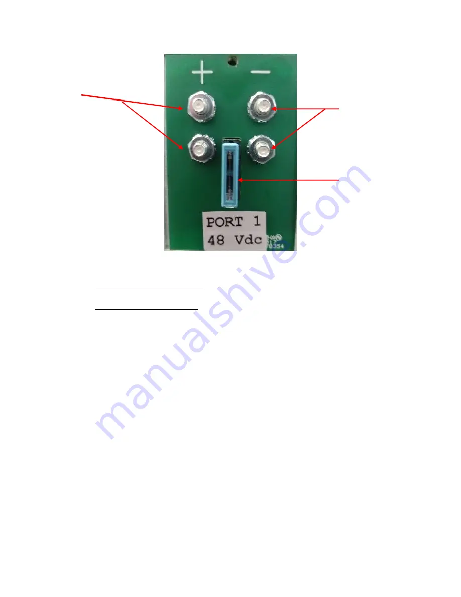
Figure 1 10/32 terminal Output Port
6.
Attach to the ACC connector – Using a standard patch cord, connect to the DC-
UPS Alarm Contact Closures via the RJ45 receptacle on the rear of the DC-UPS.
7.
Connect the AC Power Cord – Connect the attached AC power input cable to your
AC power distribution panel.
.
START UP AND CHECKOUT
Power On Checkout.
1.
Once the unit is properly mounted, you may begin the checkout procedure. First,
insure that all the equipment to be powered by the unit is installed.
2.
Turn on the AC power feed.
3.
When power is first applied, the front panel LEDs will go through a start-up
sequence of red, green and flashing yellow. The DC-UPS fans will also start-up.
4.
After the start-up sequence, the Port 1 LED will turn on green. Verify that the
connected customer equipment is receiving power.
5.
The Battery Charge Status LED will flash green. This indicates that the Battery
Pack is charging.
6.
Disconnect the AC power cord. Verify that the Battery Charge Status LED and
the System Status LED are flashing red. If there is no load on the DC-UPS this
may take several seconds. Verify that the connected equipment is still receiving
power.
7.
Reconnect the AC power cord. The Battery Charge Status LED will flash green.
This indicates that the batteries are charging.
+48Vdc Terminals
48rtn
Terminals
Output Port
Fuse


