background image

 
Electro-Pneumatic Positioner                                                                                                  SP 520 Series                                                                                                                                         

_________________________________________________________________________________________________________ 

Ver 1.20                                                                     

33                                                                 

SHIN HWA Eng.Co.,Ltd.


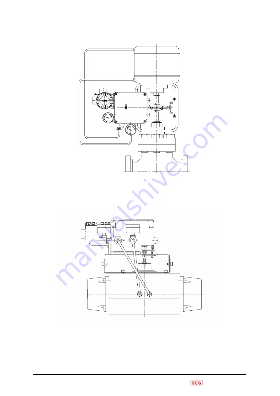
            Fig 4-3 : Double Acting Linear Actuator   

            Fig    4-4 : Double Acting Rotary Actuator   

Summary of Contents for SP520

Page 1: ...Ver 1 20 HIN HWA Eng Co Ltd INSTRUCTION MANUAL Electro Pneumatic Positioner SP520 Shin Hwa Eng Co Ltd Document No SEG SP520 ML E Date 2022 07 29 Rev No 1 20 ...

Page 2: ...ic safety Proof SP520 in danger area 5 1 10 Safety Requirements 6 2 Products Description 7 2 1 General Information 7 2 2 Main Features and Functions 7 2 3 Options 7 2 4 Label Description 7 2 5 Products Specification 10 2 6 Explosion Proof Certificate 11 2 7 Products Code 14 1 Linear type 14 2 Rotary type 15 2 8 Principle of Operation 16 2 9 Structure 18 2 10 Products Dimension 19 3 Installation 26...

Page 3: ... option Limit Switch option 39 5 7 Terminal connection for Flame explosion proof Intrinsic Safety non option 39 5 8 Terminal connection for Intrinsic safety proof Feedback option 40 5 9 Position transmitter calibration for Intrinsic Safety Feedback Option 40 5 9 1 Mode Setting 40 5 9 2 Calibration Method 41 5 10 Terminal connection for Intrinsic safety proof Feedback Limit Switch option 42 5 11 Gr...

Page 4: ... required please contact to Shin Hwa Eng Co Ltd Quality warranty is valid during the warranty period stimulated in products warranty and shall be free cost during this period only Even though it is within quality warranty period following conditions must be paid In case that customer shall maintain or repair products improper randomly In case of happening problems caused by improper movement and s...

Page 5: ...nimum supplying current is 3 2mA but maximum supplying current must not exceed into 24mA In case there is feedback option in SP520 series separated power must be supplied to feed back signal and supplying voltage must be 9 28V and not exceed into maximum 30V In order to protect products positioner internal grounding block should be grounded Please do not install the cable near high noise equipment...

Page 6: ...roof type cable gland must be used when connecting power on Ring terminal with surface area of more that 0 195 mm 2 with should be used and also M4 spring washer should be used to prevent failing out For external ground terminal ring terminal with surface area of more than 5 5 mm 2 should be used There will be risk of explosion due to electro static charge Static electricity charge may develop whe...

Page 7: ...ay be exempt from the manufacturer s liability Do not try to handle or disassemble the machine until the safety is firmly secured 1 Before maintenance or inspection of the machine make sure that no moving objects fall or move 2 Before removing the products check the safety such as taking safety action and cutting off the relative electric power and be well aware of the caution of products 3 When r...

Page 8: ... valve 2 Zero and Span adjustment are easy and convenient 3 For intrinsically safe explosion proof products a position transmitter and limit switch can be built into the positioner 4 Explosion proof products can be externally equipped with position transmitters and limit switches certified for explosion protection 5 It has excellent IP66 enclosure grade 6 Air consumption quantity is very small so ...

Page 9: ..._______________________________________________________________________________________________ Ver 1 20 8 SHIN HWA Eng Co Ltd KCs IECEx CCC ATEX Fig 2 2 SP520 Explosion proof nameplate Ex i IECEx CCC ATEX Fig 2 3 SP520 Explosion proof nameplate Ex db mb ...

Page 10: ...o specification including option Ambient Temp Indicate ambient temperature valid in explosion proof certification Serial No Indicate products serial No Explosion Proof Indicate products explosion proof grade Input Signal Indicate the range of input electric signal Supply Air Press Indicate pressure range supplying to positioner Enclosure Indicate enclosure grade of water proof and dust proof Fig 2...

Page 11: ...MPa 1 4 7 bar Explosion Proof Grade Ex db mb IIB IIC T6 T5 Gb Ex ia IIC T6 T5 Gb Ex tb IIIC T80 C T100 C Db IP66 Ex ia IIIC T80 C T100 C Db IECEx ATEX KCs CCC Enclosure IP66 Ambient Temperature Non explosion proof 20 70 C 4 F 158 F Explosion proof 20 60 C T5 T100 C 20 40 C T6 T80 C Linearity 1 F S 2 F S Hysteresis 1 F S Sensitivity 0 2 F S 0 5 F S Repeatability 0 5 F S Flow Capacity 70 LPM Sup 0 1...

Page 12: ...0406X Ambient Temperature 20 60 C T5 T100 C 20 40 C T6 T80 C 3 Type Dust explosion proof Rating Ex tb IIIC T80 C T100 C Db Certification No 22 KA2BO 0407X Ambient Temperature 20 60 C T100 C 20 40 C T80 C IECEx 1 Type Flame Proof Enclosure Rating Ex db mb IIB IIC T6 T5 Gb Certification No IECEx EPS 21 0063X Ambient Temperature 20 60 C T5 20 40 C T6 2 Type Intrinsic Safety Rating Ex ia IIC T6 T5 Gb ...

Page 13: ... 40 C T6 T80 C 3 Type Dust explosion proof Rating II 2D Ex tb IIIC T80 C T100 C Db IP66 Certification No EPS 21 ATEX 1 085 X Ambient Temperature 20 60 C T100 C 20 40 C T80 C CCC 1 Type Flame Proof Enclosure Rating Ex db mb IIB IIC T5 T6 Gb Certification No 2022122307115730 Ambient Temperature 20 60 C T5 20 40 C T6 2 Type Intrinsic Safety Rating Ex ia IIC T5 T6 Gb Ex ia IIIC T80 C T100 C Db Certifi...

Page 14: ...ment No 2021 22 of Ministry of Employment and Labor CCC CQM10 C2301 2022 Implementation Rule for China Compulsory Certification CC22 001 20220429 Notification for transition of GB T Series standards Intrinsic Safety Explosion Proof Specification Intrinsic Safety Explosion Proof Specification I EC 60079 0 2017 I EC 60079 11 2011 Explosion Proof Class Ex ia IIC T6 T5 Gb Barrier Specifications Ui Ii ...

Page 15: ... Position transmitter 4 20mA DC 0 1 Explosion Proof Type Non explosion type IP66 Ex db mb IIB IIC T6 T5 Gb Ex ia IIC T6 T5 Gb Ex ia IIIC T80 C T100 C Db Ex tb IIIC T80 C T100 C Db IP66 N D A T Explosion Proof type Specification None IP66 KCs IECEx ATEX CCC 0 1 2 3 4 Connection Air Rc PT 1 4 Conduit G PF 1 2 Air NPT1 4 Conduit NPT1 2 Air NPT1 4 Conduit M20x1 5 G N M Position L S None 0 Orifice None...

Page 16: ...ia IIC T6 T5 Gb Ex ia IIIC T80 C T100 C Db Ex tb IIIC T80 C T100 C Db IP66 N D A T Explosion Proof type Specification None IP66 KCs IECEx ATEX CCC 0 1 2 3 4 Connection Air Rc PT 1 4 Conduit G PF 1 2 Air NPT1 4 Conduit NPT1 2 Air NPT1 4 Conduit M20x1 5 G N M Position L S None 2 SPDT External Type 0 1 2 Orifice None 1 2 0 1 2 Optionable items 1 Non Explosion Proof Feedback L S Feedback L S External ...

Page 17: ... the gap between the nozzle 17 and the spring support 5 is opened and the pressure in the nozzle pressure chamber 18 drops resulting in a pressure difference with the pressure chamber 19 Accordingly Spool 9 pushes Poppet A 12 to open port A and the output of OUT1 raises the diaphragm valve 3 valve to the top In accordance with this movement the Feedback Lever 20 moves upward and transmits it to th...

Page 18: ... pushes Poppet A 12 to open port A and the output of OUT1 pushes Actuator 3 to the right rotates actuator stem 21 and is transferred to Cam 20 According to this movement the Span Lever 6 is moved and the spring support 5 is pulled through the Span lever spring 14 and the gap between the nozzle 17 and the spring support 5 becomes narrow again and port A is closed and the output of out1 This stoppin...

Page 19: ...es _________________________________________________________________________________________________________ Ver 1 20 18 SHIN HWA Eng Co Ltd 2 9 Structure 1 LINEAR TYPE 2 ROTARY TYPE Fig 2 7 LINEAR TYPE Schematic Fig 2 8 ROTARY TYPE Schematic ...

Page 20: ...r SP 520 Series _________________________________________________________________________________________________________ Ver 1 20 19 SHIN HWA Eng Co Ltd 2 10 Products Dimension Fig 2 9 SP520 LINEAR TYPE Non Explosive Proof Type ...

Page 21: ...atic Positioner SP 520 Series _________________________________________________________________________________________________________ Ver 1 20 20 SHIN HWA Eng Co Ltd Fig 2 10 SP520 LINEAR TYPE Explosive Proof Type ...

Page 22: ...ic Positioner SP 520 Series _________________________________________________________________________________________________________ Ver 1 20 21 SHIN HWA Eng Co Ltd Fig 2 11 SP520 Rotary TYPE Non Explosive Proof Type ...

Page 23: ...umatic Positioner SP 520 Series _________________________________________________________________________________________________________ Ver 1 20 22 SHIN HWA Eng Co Ltd Fig 2 12 SP520 Rotary TYPE FORK LEVER Type ...

Page 24: ...Pneumatic Positioner SP 520 Series _________________________________________________________________________________________________________ Ver 1 20 23 SHIN HWA Eng Co Ltd Fig 2 13 SP520 Rotary TYPE Namur Type ...

Page 25: ...atic Positioner SP 520 Series _________________________________________________________________________________________________________ Ver 1 20 24 SHIN HWA Eng Co Ltd Fig 2 14 SP520 Rotary TYPE Limit Switch Option ...

Page 26: ...tioner SP 520 Series _________________________________________________________________________________________________________ Ver 1 20 25 SHIN HWA Eng Co Ltd Fig 2 15 SP520 Rotary Type External L S External Feedback Option ...

Page 27: ...y not be mixed with oil water and different material When installing positioner safety work is required after input signal and air pressure are shutdown 3 2 Tools for Installation Hex Wrench set screw drivers Spanners for hexagonal head bolts 3 3 Linear Positioner Installation Linear positioner shall be installed and used on linear motion valves such as glove or gate vale type which uses spring re...

Page 28: ...dard lever type positioner installation steps Fig 3 2 SP520 Positioner Installation on actuator Assemble with the enclosed bracket and bolts Connect a bracket onto actuator yoke with bolts Tighten bolts loosely so that they may be modified location easily Connect air filter regulator to an actuator temporarily And then decrease slowly supplying air pressure and valve stroke shall be reached into 5...

Page 29: ...bar located on actuator clamp should be inserted into spring position on feedback lever s hole as seen as figure Check whether positioner feedback lever is levelled at valve 50 stroke Unless it is levelled adjust it horizontally after moving a bracket or positioner body Fig 3 3 SP520 positioner installation on actuator Fig 3 4 connection bar Insert method between lever and spring Stroke 30mm ...

Page 30: ...ar in overall stroke value and feedback value s equal point If positioner lever and actuator connection bar has not consistent move and reset positioner bracket or connection bar Stroke 30mm After checking above caution contents and drawing and fabricate bracket so that it may be fixed actuator as following figure Fig 3 5 When valve position is 50 it shows installed lever vertically Fig 3 6 Connec...

Page 31: ...SHIN HWA Eng Co Ltd In case that positioner was installed in bracket normally lever should not be touched in positioner stopper on full close and full open position When lever shall be touched on positioner stopper it may be malfunction so after installing please check installation status Fig 3 7 SP520 Bracket insert method Fig 3 8 SP520 lever and stopper s gap ...

Page 32: ... and Namur type 3 4 1 Fork Lever type Installation Please attach lever set enclosed on packing to positioner main axis and shaft and install so that positioner shaft and actuator axis may be concentric Fig 3 9 Fork Lever Type Installation 3 4 2 Namur Type Installation Please Install the positioner on the upper part of the positioner mounting bracket align the groove of the actuator main shaft with...

Page 33: ...an actuator operation pressure or actuator spring operation pressure 4 2 Connection Piping with actuator 4 2 1 Single Acting actuator Single acting positioner should use OUT 1 port only Therefore in case of using a single type spring return actuator make sure to connect positioner s OUT1 port and actuator s supply pressure port 4 2 2 Double Acting actuator Double acting positioner uses both OUT1 a...

Page 34: ...r SP 520 Series _________________________________________________________________________________________________________ Ver 1 20 33 SHIN HWA Eng Co Ltd Fig 4 3 Double Acting Linear Actuator Fig 4 4 Double Acting Rotary Actuator ...

Page 35: ...___________________________________ Ver 1 20 34 SHIN HWA Eng Co Ltd 4 3 Air Connection per each actuator type 4 3 1 ROTARY TYPE Forward Operation Reverse Operation Input Current Increasing Actuator Axis CW Rotation Input Current Increasing Actuator Axis CCW Rotation D o u b l e A c t i n g S i n g l e A c t i n g ...

Page 36: ...______________________________________________________ Ver 1 20 35 SHIN HWA Eng Co Ltd 4 3 2 LINEAR TYPE Forward Operation Reverse Operation Input Current Increasing Cylinder rod Arrow Direction Input Current Increasing Cylinder rod Arrow Direction D o u b l e A c t i n g S I n g l e A c t i n g ...

Page 37: ...xplosion proof type cable and packing union must be used in danger area such as explosive gas zone and in case of using electric cable gasket and shield should be used and they must be sealed completely In case of using flame explosion proof packing union it is required to select inside rubber packing size properly which meets on cable outside size While power is on do not open cover which is conn...

Page 38: ... in wire pipe inlet and keep the closure after complete sealing with full of compound method The installation of compound filled internal pressure explosion proof wires shall conform to the requirements of IEC 60079 14 14 4 conduit systems 5 4 Terminal connection for non explosion proof Non option Open the upper cover and connect correctly outside inlet wire on terminal block Fig 5 1 Flame Proof E...

Page 39: ...cover 5 5 Terminal connection for non explosion proof Feedback option Unscrew the set screw of the terminal box open the terminal box cover and connect it to the position of the terminal block in the terminal box according to the external input line and Connect the FEEDBACK SIGNAL line to Connect the ground wire to the ground wire Close the terminal box cover and tighten the set screw again to fix...

Page 40: ...option Limit Switch option 5 7 Terminal block connection for Flame explosion proof Intrinsic Safety non option Open the terminal box cover by loosening the set screw of the terminal box and connect the external input wires and to the and positions of the terminal block in the terminal box Connect the ground wire Close terminal box cover and tighten set screw again and fix terminal cover Fig 5 6 Te...

Page 41: ... terminal box cover and connect it to the position of the terminal block in the terminal box according to the external input line and Connect the FEEDBACK SIGNAL line to Connect the ground wire to the ground wire Close the terminal box cover and tighten the set screw again to fix the terminal cover Fig 5 7 Terminal Connection for Intrinsic Safety Proof type Feedback option 5 9 Position transmitter...

Page 42: ...s basically In case that LED extinguish fast POTENTIOMETER status pass off range value than ZERO SPAN Setting value First set LOCK 2POINT 5POINT s MODE 4mA 8mA 12mA 16mA 20mA setting Position the valve at 0 25 50 75 100 respectively and press each switch for 3 seconds to set At this time the LED flashes 3 times and then the default State when setting 2POINT ZERO SPAN s value adjustment can be swit...

Page 43: ...fety Proof type Feedback Limit Switch option The circuit of the intrinsically safe device must be separated from the general circuit Keep the current parameter below the specified value indicated on the explosion proof certification Conduct appropriate grounding for the installation site and maintain the ground resistance of the product and barrier with an equal potential Fig 5 9 Terminal Connecti...

Page 44: ...ent and ZERO setting method From Calibrator input 4mA current rotate ZERO adjustment screw and adjust so that that valve position may be in 0 From Calibrator input 20mA current rotate ZERO adjustment screw and adjust so that that valve position may be in 100 When adjusting by turning the SPAN adjusting screw the position of 0 adjusted in the above step changes so repeat the step once again When ad...

Page 45: ... again to fix it 6 3 AUTO MANUAL conversion screw setting method The auto manual switching screw is located on the upper part of the pilot valve and serves to bypass the positioner If you loosen the lock screw on the upper part of the pilot valve and turn the auto manual switch screw in the M direction counterclockwise the supply pressure supplied to the positioner enters the actuator as it is reg...

Page 46: ...rom the factory So do not arbitrarily adjust 6 4 Orifice setting method If the actuator capacity is very small compared to the flow rate of the positioner capacity less than 180cm 3 hunting may occur so an orifice can be installed on the pilot valve Remove the O ring from OUT1 and OUT2 located under the pilot valve insert the orifice 1mm or 2mm and then assemble the O ring again If you select orif...

Page 47: ...s clogged by foreign substances such as dirt and oil so it must be cleaned Loosen the lock screw on the upper part of the pilot valve remove the auto manual switching screw make a hole with a steel wire of 0 3mm or less wash it and assemble it again 7 Error Check and solution method 7 1 Basic check point when positioner does not operate Supply pressure check point Over Min 1 4 kgf cm 2 Input signa...

Page 48: ...oosing Nozzle block Solution method Check signal connection wire status Auto manual conversion screw fixing Nozzle check and washing Check point When hunting works in a short cycle W hen hunting works in a long cycle Cause Actuator capacity is small On actuator and valve Friction is happening greatly Solution method Equip orifice on Pilot valve OUT1 OUT2 outlet Action on friction decreasing Increa...

Page 49: ... condition ZERO SPAN setting Check supplying pressure Cause Lever status is not horizontal in 50 ZERO SPAN setting non correct Supplying pressure does not constant Solution method Lever s horizontal installation ZERO SPAN Re adjustment Check supplying pressure such As regulator Check point Check FEEDBACK lever and connection bar installation s condition Cause Happening on FEEDBACK lever and connec...

Page 50: ..._________________________________________________________________________ Ver 1 20 49 SHIN HWA Eng Co Ltd SHINHWA ENG Co Ltd Address 80B 2L Cheongneung daero Namdong gu Incheon 21695 Korea Tel 82 32 817 8030 Fax 82 32 815 8036 e mail 8030 seg co kr homepage http www seg co kr ...

Reviews: