39
TB MRD1-G 11.97 E
5.3.8
Validity check
The
MRD1
is provided with a special parameter chec-
king facility as protection against wrong settings. Ho-
wever, to prevent that the actual setting range is too
much restricted , this facility can only protect against
gross setting errors. Before they are stored, changed
settings are checked for their mutual validity. The pro-
cedure is such that firstly the parameters are compared
to the calculated rated currents I
N
(per winding) of the
component, which result from the rated apparent po-
wer and rated voltage. Thereafter interrelation of the
parameters is checked.
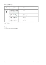
If there is a discrepancy when setting parameters via
the keyboard, either the
MRD1
does not allow the
respective value to be further changed or refers to the
inconsistent value by issuing a clear text message
when trying to store the parameter. In this case the
EDIT mode is not left and the value can be corrected.
When setting parameters via an interface, validity er-
rors are indicated by a spezial telegramm message.
A setting is not regarded to be valid if one of the fol-
lowing conditions are not met :
•
CT mismatch for each winding
1/8
×
I
N
< I
WPN
< 2
×
I
N
•
CT transformation ratio at
MRD1
rated current I
WPN
<
5 A
•
Relation of voltage levels
For three-winding transformers (
MRD1-T3
)
U
N
Winding
1
≥
U
N
Winding
2
≥
U
N
Winding 3
For two-winding transformers (
MRD1-T2
)
U
N
Winding
1
≥
U
N
Winding
2
•
Tripping characteristic
Id(I
S
=0)
≤
Id(I
S
=2)
i.e.gradient
Sector I
≥
0
and
gradient
Sector I
≤
gradient
Sector II
•
Ext. Blockage
t
min
> t
max
minimum hold time is greater than maximum hold
time
Abbreviations :
Abbreviations :
Abbreviations :
Abbreviations :
S
N
set rated vector power
U
N
set rated component voltage (phase-to-phase voltage)
I
N
rated component current (I
N
= S
N
/(
√
3 x U
N
)) calculated from U
N
and S
N
I
WPN
set rated C.T. primary current
Gradient
characteristic gradient in the respective linear sector (see chapter 5.3.4)

