background image


Ver. 1.0 

SHIN HWA Eng.Co.,Ltd. 

MOTOR CYLINDER 
 

MS1K~MS1T, M1K~M50T 


1  Product Description 

1-1 General 

  Introduction 

The Motor cylinder is completely enclosed structure, consisting of an overload safety device 
(automatic stroke setting) by actuation of a compression spring, a highly efficient lead screw, 
a fully closed type motor combined with a precision reduction gear unit. 
Therefore, careful handling of the Motor cylinder is necessary. 

  Inspection and checks 

-  Does the nameplate match the order? 

-  Is there any damage during transportation? 

-  Are all tightening bolts fastened with sufficient force? 

-  In case there are any troubles, please check the model, serial number, situation and contact 

us immediately. 

1-2 Operation principle 

  The screw shaft rotates by the rotation of the motor. 

At this time, the Piston rod assembled with the nut operates a linear restraining motion within 
the set stroke range, and the load reciprocates in forward and reverse rotation of the motor. 
According to type, the required movement speed can be obtained by adjusting the pitch of the 
screw and the reduction ratio of the reduction gear device. 

1-3 Motor cylinder used 

  Used for elevating and lowering, reciprocating, compression and traction by linear motion 

  Compressing Stop 

It can also be used for devices requiring continuous compressive force or pulling force by 
the operation of a built-in spring, and can be safely stopped without mechanical overload by 
the operation of the spring and the limit switch. 

  Retaining Load 

When the load is applied even after Motor cylinder in operation is stopped, there are two 
ways in which the load from the stop position can be maintained. 
First, the way to keep the screws locked on the brakeless type. 
Second, the way of maintaining the load by the braking force by the brake attachment. 

(Holding load 

  Applied load 

×

1.2 ) 

  Arbitrary Stroke Setting 

In the type with an external or internal limit switch set, the stroke can be arbitrary set and 
used by adjusting the position of the limit switch operation cam within the entire stroke range. 

  Inching Movement 

When the Motor cylinder is installed or used, the inching movement on the stroke is also 
available for every of our products. 
In the type with no brake, there is some difficulty in stopping at the correct position due to 
the inertia of the rotor inside the motor. 


Summary of Contents for M1K

Page 1: ...MOTOR CYLINDER MS1K MS1T M1K M50T Ver 1 0 SHIN HWA Eng Co Ltd MOTOR CYLINER INTRUCTION MANUAL MS1K MS1T M1K M50T Shin Hwa Eng Co Ltd ...

Page 2: ...f Limit Switch 9 Potentiometer Type 10 2 2 INSTALLATION 11 Storage 11 Installation Place 11 Installation Method 11 Piston rod Installation 12 Bellows Attaching 13 Stroke Setting 14 Cautions 14 Brake structure and manual operation 15 2 3 ELECTRIC WIRING 16 Wiring method 16 Limit Switch Circuit Diagram For Overload 16 Position control 17 Cam switch Setting method 17 Basic Operation Circuit Diagram S...

Page 3: ...g Co Ltd MOTOR CYLINDER MS1K MS1T M1K M50T Overload 19 Frequency in Use 19 3 2 MAINTENANCE 20 Grease lubrication 20 Overhaul 20 Lubrication Cycle to Screwed Shaft 20 Recommendable Greases 20 Lubrication to Screwed Shaft 20 ...

Page 4: ...w and the reduction ratio of the reduction gear device 1 3 Motor cylinder used Used for elevating and lowering reciprocating compression and traction by linear motion Compressing Stop It can also be used for devices requiring continuous compressive force or pulling force by the operation of a built in spring and can be safely stopped without mechanical overload by the operation of the spring and t...

Page 5: ...4 0 75 1 5 2 2 Stroke mm 200 600 200 1 000 200 1 500 Thrust Load kg 6 000 8 000 10 000 13 000 16 000 20 000 Speed mm sec ML 18 15 12 12 10 15 MM 30 36 30 36 30 20 Motor Power kW ML 1 5 1 5 1 5 2 2 2 2 3 7 MM 2 2 3 7 3 7 5 5 5 5 5 5 Stroke mm 300 3 000 Construction Totally enclosed outdoor type Insulation Class B Class Ambient Temperatur e 15 C 50 C Rating 30min 25 ED Relative humidity 85 이하 Brake ...

Page 6: ...Speed Screw A Acme Screw B Ball Screw Rated Thrust load 5K 500kg 1T 1000kg Stroke 01 100mm 10 1000mm Bellows With J Without None Potentiometer With P Without None Limit Switch L In Door T Out Door Installation method C Column K Clevis Specification O Standard N Special S Straight L Low M Medium H High D Damper Position Control ...

Page 7: ...7 Ver 1 0 SHIN HWA Eng Co Ltd MOTOR CYLINDER MS1K MS1T M1K M50T 2 Product installation 2 1 Structures MS Type ...

Page 8: ...8 Ver 1 0 SHIN HWA Eng Co Ltd MOTOR CYLINDER MS1K MS1T M1K M50T M D L M H Type ...

Page 9: ...9 Ver 1 0 SHIN HWA Eng Co Ltd MOTOR CYLINDER MS1K MS1T M1K M50T Position of Limit Switch Internal limit switch type External limit switch type 외부 LIMIT ...

Page 10: ... product is configured as a two stage reduction gear The high speed part uses a helical gear and the low speed part uses a spur gear to ensure forward and reverse operation and sufficient life Thrust Limiter Unit With the action of the compressed spring and limit switch it can be safely stopped at any position in both directions in case of overload Linear Safety Device It is a device that moves th...

Page 11: ...sure to confirm the temperature limit for each type The operating temperature range is 15 C to 50 C When using it at higher temperatures a heat dissipating cover must be attached Outdoor type with Bellows is recommendable for use in bad atmospheres If you install it outdoors tighten the terminal box cover and the conduit connection cable completely after the electrical connection And make sure tha...

Page 12: ...uld be attached to the product at installation And when the Motor cylinder is operated in the unattached state the Piston rod rotates and the fixed Bellows is damaged There are two ways to manually adjust the stroke when installing by turning the manual handle shaft and adjusting the Piston rod The Piston rod reciprocates according to the rotation direction If the Bellows is attached make sure tha...

Page 13: ...ton rod Move the Piston rod to end of the Piston rod by manual or electric operation At this time the Bellows will be shrunk so the cylinder side is fixed with a band Then with the Bellows shrunk clamp the band on the Piston rod side Fitting the Bellows shrunk too much may cause its breaking Unscrew the Set Screw with a L wrench and disassemble the Knuckle joint Fig 1 After putting new Bellows tig...

Page 14: ... the heading direction can be stopped in both directions by the operation of the limit switch attached to the outside If the motor brake is not attached it is difficult to accurately stop at a desired position due to the rotational inertia If the brake attached type is used the motor can be stopped at a more accurate position Cautions The switch box of the thrust limiter unit and the wire connecti...

Page 15: ...coil spring in the Yoke always pushes the armature when the power is cut off and the flange disk is squeezed by the force based on the fixed plate and the rotating part is braked by the frictional force Conversely when power is supplied to the electronic coil the Armature is squeezed with a stronger force than the spring biasing force Therefore a space is formed between the flange ring and the Arm...

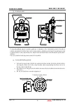
Page 16: ... flexible tubes are unavoidably used it should be completely watertight but the connection part should be sealed with liquid packing Three Bond No 2 Limit Switch Circuit Diagram For Overload Five point Switch Standard LSF Terminal 1 2 Normally ON but OFF for continuous pushing at the end of stroke and in case of overload while the Piston rod is extending LSF Terminal 1 4 Normally OFF and it is ON ...

Page 17: ...ntermediate shaft of the Motor cylinder decelerator and the Piston rod is reciprocated by attaching a limit switch operating cam and a potentiometer to the output shaft the output shaft will rotate forward and backward within 300 rotation Then the position detecting device detects the position Connect the main body of the Motor cylinder and the knuckle joint to the other machine and stop the Pisto...

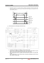
Page 18: ...roke by adjustment of the Positioning limit switch operation cam it can be used in the entire stroke range by the operation of the overload safety device The basic circuit diagram of the Motor cylinder is shown below Various kinds of controls are available by using an external command switch or a push button as an operational switch depending upon desired operations When the PBF switch is ON the P...

Page 19: ...verload When the Motor cylinder is used if a load has reached the limit or the large inertia body is moved the overload device may be activated when the motor starts In this case reduce the load Frequency in Use The heat capacity of the motor cylinder is well afforded However the operational frequency will be limited because of its reciprocating movement Calculate the tolerable operational frequen...

Page 20: ...wo years or after 100 thousand times Sliding Bearings 50 100 Application to the surface each two years or at every routine inspection Overhaul Overhaul should be made every two years of after 100 thousand times Lubrication Cycle to Screwed Shaft Operational frequency Cycle 700 times or more day 1 month 100 700 times day 1 month to half a year 10 100 times day 6 months to 1 year Recommendable Greas...

Page 21: ...Ltd Manufacturer information Company Name SHIN HWA ENG Co Ltd Address 242 Cheongneungdae ro 80B 2L Namdong gu Incheon Korea ZIP CODE 21695 Tel 82 32 817 8030 Fax 82 32 815 8036 E mail 8030 seg co kr Website http www seg co kr COPYRIGHT 2020 C Shin Hwa Eng Co Ltd ALL RIGHTS RESERVED ...

Reviews: