16
Ver. 1.0
SHIN HWA Eng.Co.,Ltd.
MOTOR CYLINDER
MS1K~MS1T, M1K~M50T
2-3 ELECTRIC WIRING
Wiring method
In wiring the Motor cylinder give special care to the following points
- Since the cylinder itself swings around the Trunnion shaft during operation, it is preferable
to use flexible cabtyre cables for wiring.
- When the outdoor type is installed, the motor and the brake terminal box can be assembled
by rotating them by 90 degrees, so that it is preferable that the electric wire outlet is installed
downward.
- In principle, it is not recommended to use flexible tube. If flexible tubes are unavoidably
used, it should be completely watertight, but the connection part should be sealed with liquid
packing (Three Bond No.2)
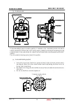
Limit Switch Circuit Diagram (For Overload)
- Five-point Switch (Standard)
LSF Terminal 1-2 : Normally ON, but OFF for continuous pushing at the end of stroke
and in case of overload while the Piston rod is extending.
LSF Terminal 1-4 : Normally OFF, and it is ON when overload continues
(For signal check)
LSR Terminal 1-3 : Normally ON, but OFF for continuous drawing at the end of stroke in
case of overload while the Piston rod is retracting.
LSR Terminal 1-5 : Normally OFF, and it is ON when overload continues.
(For signal check)
LSF
LSR
L/S
Reverse
L/S
Forward
Φ
Φ
Φ
Φ
Φ
GREEN 5
RED 3
WHITE 2
YELLOW 4
F-FORWORD
R-REVERSE
1 BLACK


