Maintenance
GDH Series Direct Fired Ducted Heater
Page 13 of 16
S
ERVICE
This work should only be carried out by authorized personnel
1.
Check air supply source and ensure the proper amount of air is going through the heater.
2.
Turn off power and gas supply and remove service panel at rear of heater. Check and clean main burner
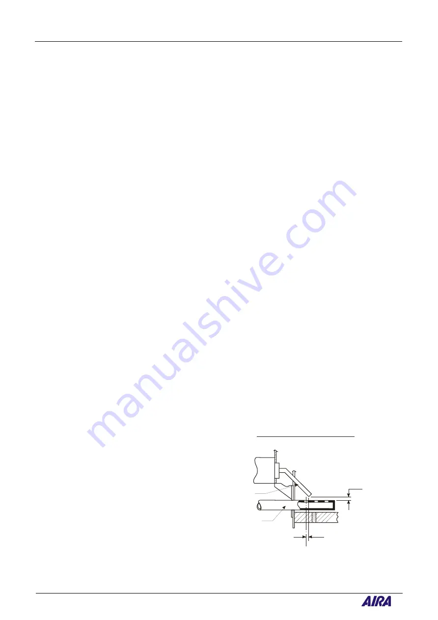
as necessary. Check and clean pilot burner assemblies. Adjust ignition electrode as shown in Figure 2.
Clean observation port glass. Refit service panel.
3.
Remove UV cell. Clean and inspect.
4.
Fit manometer to valve train and pressure test in the following stages:
4.1.
Fit manometer to test point between isolating vale and heater valve train.
Leave valve closed –
No pressure means isolating vale is not leaking.
4.2.
Pressure test between isolating valve and first safety shut off valve/
4.3.
Pressure test between safety shut-off valves.
5.
Turn power and gas supplies on and start heater. With soap and water leak test all fittings and valves.
6.
Fit manometer to burner pressure test point. Turn heater on and while burner is in pre-purge period,
zero manometer to the new liquid level created by positive air pressure exerted on the burner. When
burner starts, check and if necessary set burner pressure as stated on data plate.
7.
Check all safety controls.
7.1.
Turn all gas off at isolating valve. Burner must stop. Burner control must go to flame failure de-
energising all safety shut-off valves.
7.2.
Check and ensure high limit control breaks, locking out burner at a maximum temperature of 80°C.
7.3.
Fit low scale manometer to pressure test points on air pressure switch. A differential pressure of
between 110 to 160 Pa will indicate sufficient air velocity across the burner. Reduce air flow
through heater, check cut-out differential pressure – should be between 60 and 70 Pa. Slightly
increase air volume until air pressure switch makes and burner starts. Ensure burner is operating at
rated capacity.
Using a suitable combustion test kit, take a CO-CO
2
reading from a warm air register. Heater must
not produce more than 10 ppm CO and 3000 ppm CO
2.
CO-CO
2
ratio must no exceed .003.
Note that in some industrial locations background air may contain detectable amounts of CO and
CO
2.
These amounts must be deducted from those generated by the heater.
7.4.
Allow air volume to reach normal
capacity. Recheck CO
2.
7.5.
Record CO-CO
2
readings on combustion
check card. Sign and date entry.
8.
Ensure all pressure test point screws are
firmly secured.
9.
Check remote controls and ensure correct
operation e.g. Time lock, thermostat and
selector switch.
10.
Ignition electrode setting – see Fig. 2
PILOT ELECTRODE SETTING
PILOT TUBE
SPARK ELECTRODE
c
L
OF PILOT TUBE FIRST PORT
2 mm SPARK GAP
2 mm
LOCATE EDGE OF SPARK ELECTRODE
2 mm FORWARD OF OF FIRST PILOT
PORT AS SHOWN
c
L
Fig. 2


