background image


SARK-110


User’s 

Manual


Rev 1.3.8 30 July 2018  

- 22 - 

© 2011-2018, Melchor Varela 

 EA4FRB 

to a PC for further analysis using SARK Plots or the ZPLOTS Excel application, available from 

http://www.ac6la.com/zplots.html

. 

Use Navigator A to select 

«FILE»

 in the main menu for data file operations. 

Press the Select 

[

button to activate the File popup submenu. Use Navigator B to highlight the 

desired submenu File option. 

«Save Data File»


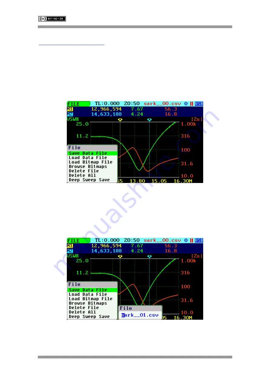
The Save Data File option enables the current measured data to be saved for further review: 


After  selecting  the 

«Save  Data  File»

  submenu  option,  enter  the  file  name.  By  default,  the  file 

name  has  the  format  “sark

_

_xx.csv”


(or  “sark_

_xx.

tdr”  for  Cable  Test  mode)

,  where  xx  is  an 

automatically  assigned  number.  To  change  the  file  name,  use  Navigator  B  to  change  the 

character  value  and  Navigator  A  to  change  the  character  position  highlighted  in  inverse video. 

Press  the  Select 

[

]

  button  to  validate  the  selection.  Press  any  other  button  to  cancel  the 

operation.  


The 

«Save  Data  File» 

option  can  be  also  selected  by  pressing  Navigator  A  when 

«FILE» 

is 

highlighted. 

Summary of Contents for 109990076

Page 1: ...ess mainly focus on the distribution of electronic components Line cards we deal with include Microchip ALPS ROHM Xilinx Pulse ON Everlight and Freescale Main products comprise IC Modules Potentiometer IC Socket Relay Connector Our parts cover such applications as commercial industrial and automotives areas We are looking forward to setting up business relationship with you and hope to provide you...

Page 2: ...ed under a Creative Commons Attribution NonCommercial ShareAlike 3 0 Unported License Melchor Varela EA4FRB 2011 2018 SARK 110 Vector Impedance Antenna Analyzer User s Manual Revision 1 3 8 Updated to Firmware Version 0 10 x ...

Page 3: ...0 2 4 MAIN MENU 11 2 5 CHANGING THE FREQUENCY 13 2 6 CHANGING THE SPAN 14 2 7 CHANGING THE START AND STOP FREQUENCIES 15 2 8 FREQUENCY PRESETS 16 2 9 USING MARKERS 17 2 10 CHANGING THE VERTICAL AXIS PARAMETER 21 2 11 SAVING AND RECALLING MEASUREMENTS 21 2 12 TAKING SCREENSHOTS 27 2 13 CHANGING THE OPERATING MODE 28 2 14 CHANGING THE SETTINGS 28 3 OPERATING MODES 43 3 1 SCALAR CHART MODE 43 3 2 SMI...

Page 4: ... 74 4 2 2 Capacitor 77 4 2 3 Quartz Crystal 78 4 2 4 Transmission Line 80 4 3 TUNING STUBS 83 APPENDIX A THEORY OF OPERATION 85 APPENDIX B FUNDAMENTAL PARAMETERS 87 APPENDIX C UPGRADING THE FIRMWARE 89 APPENDIX D OSL CALIBRATION 90 APPENDIX E FREQUENCY CALIBRATION 95 APPENDIX F DETECTOR CALIBRATION 96 APPENDIX G FREQUENCY PRESETS FILE 100 APPENDIX H SCALE PRESETS 101 APPENDIX I CUSTOM CABLE SETTIN...

Page 5: ...rement reference plane is automatically adjusted via the Open Short Load calibration procedure for higher measurement accuracy Also the analyzer implements a transmission line addition or subtraction feature in order to make antenna measurements while discounting the effect of the feed line The user interface based on a color display has been designed to be intuitive and easy to use The graphical ...

Page 6: ...Cable Test TDR Field Mode Multi band Signal Generator Computer Control and Band Scan Good accuracy over a broad range of impedances Resolves the sign of the impedance Manual and automatic positioning tracking markers Internal 2MB USB disk for the storage of measurements screenshots configuration and firmware upgrade Exports data in ZPLOTS compatible format for further analysis on a PC SARK Plots c...

Page 7: ...he right side facilitates connection to a personal computer for communication and internal battery charging using a compatible mini USB cable not included The unit charges the internal battery when connected to USB The internal battery charger automatically manages the charge cycle and stops the process when the battery is fully charged The complete charge cycle takes around 3 5 hours Slide the Po...

Page 8: ...connect the antenna 3 Maximum safe RF input is 2V peak 16 dBm Exceeding this RF level may damage the unit Note that powerful active transmitters nearby may induce a high RF voltage on the antenna 4 Test port is DC coupled Use an external series capacitor for measurement scenarios whereby a DC voltage is present 5 This product emits a low power RF signal during its active measurement mode When conn...

Page 9: ...same for all operating modes of the SARK 110 Screen layouts that show specifics for each operating mode are provided in corresponding sections of this manual 1 Diagram 10 Transmission Line length setting 2 Traces 11 Reference impedance setting 3 Markers 12 Calibration profile 4 Vertical axis labeling 13 Filter setting 5 Horizontal axis labeling 14 Sampling setting 6 Active main menu option 15 Cali...

Page 10: ... USB Battery status Device operating from USB Battery charge status when operating from battery Disk Disk write operation in progress Zoom Smith Chart Zoom E Zoom Extends Zoom 1o Zoom 1st Octave Zoom 1s Zoom 1st Sixteenth Zoom nq Zoom 1st to 4th n Quarter Sampling d s Double sampling r 2 Normal sampling resolution r 4 Normal sampling resolution r 8 Normal sampling resolution 1 8 Filter ave Average...

Page 11: ...on is used to control the operating state of the SARK 110 Running or Holding In the holding state the signal generator and measurement circuits are inactive Ø Note when loading a stored data file the analyzer is automatically placed in a holding state Select The button is used to activate the popup submenu associated with the highlighted option and for selecting the desired option within the popup...

Page 12: ...te and settings are saved automatically Save Conf button can be used to launch Mode menu 2 4 Main Menu The main menu is the primary navigation tool Navigator A is used to change the active menu option If the Main Menu setup option is enabled a popup menu is shown automatically when the Navigator A right or left buttons are pressed see the screenshot below The active menu option is shown on the top...

Page 13: ...SARK 110 User s Manual Rev 1 3 8 30 July 2018 12 2011 2018 Melchor Varela EA4FRB ...

Page 14: ...FREQ Then use Navigator B to change the frequency The frequency will change according to the current frequency multiplier that is highlighted in reverse video Use Navigator A to change the frequency multiplier position if needed Press the Select button to validate the frequency selection Press any other button to cancel the operation The screenshot below is of the frequency edit dialog showing the...

Page 15: ... 6 Changing the Span There are two methods of editing the Span i Use Navigator A to select SPAN in the main menu Press the Select button to display the popup dialog associated with SPAN Then use Navigator B to change the span The span will change according to the current span frequency multiplier that is highlighted in reverse video Use Navigator A to change the span frequency multiplier position ...

Page 16: ...e FREQ and SPAN entry mode The screenshot below shows the main menu changed to allow the entry of START and STOP frequencies Operation is similar to the FREQ or SPAN entry i Use Navigator A to select START or STOP in the main menu Press the Select button to display the popup dialog Then use Navigator B to change the frequency The frequency will change according to the current frequency multiplier ...

Page 17: ...luding the amateur radio bands and other suitable settings Use Navigator A to select PRESET in the main menu Press the Select button to activate the Preset popup submenu Use Navigator B to highlight the desired preset Press the Select button to validate the preset selection Press any other button to cancel the operation See in the screenshot below the available presets ...

Page 18: ...ation window in blue background shows the frequency or distance in cable test mode and the two values that correspond to the plotted values at each of the markers Use Navigator A to select either MARK 1 or MARK 2 in the main menu Press the Select button to activate the Marker popup submenu Available options are Enable for activating or deactivating the marker Tracking for selecting the tracking mo...

Page 19: ...WR and Marker 2 to track the crossovers on the 50 ohm impedance value MARK 2 Tracking Cross Any Z 50 0 You could also program the unit to detect the bandwidth by setting MARK 1 Tracking Cross Down VSWR 2 0 and MARK 2 Tracking Cross Up VSWR 2 0 Navigator B will be used to move to the different detection points except for the Max and Min tracking modes where logically there is only a single detectio...

Page 20: ...e possible use of this feature is determining the VSWR bandwidth of an antenna Besides the display includes the calculation of electrical length of a line that will be useful for applications such as tuning stubs see section 4 3 The Info option can be also selected by pressing Navigator A when either MARK 1 or MARK 2 are highlighted The Center menu option can be used to set the center frequency at...

Page 21: ... is the new Data menu option that allows selecting the data to the display at the marker position The choices are the Plot Values Z in rectangular notation Z in polar notation Rho in rectangular notation or Rho in polar notation As an example the screenshot below shows the marker 1 set to display Z in rectangular form ...

Page 22: ...ivate the LeftY or RightY popup submenu Use Navigator B to highlight the desired submenu parameter option Press the Select button to validate the selection Press any other button to cancel the operation The screenshot below shows the available parameters for the vertical axis ii Use Navigator B when either the LEFT Y or RIGHT Y option is highlighted Options are selected sequentially 2 11 Saving an...

Page 23: ...ata File option enables the current measured data to be saved for further review After selecting the Save Data File submenu option enter the file name By default the file name has the format sark__xx csv or sark__xx tdr for Cable Test mode where xx is an automatically assigned number To change the file name use Navigator B to change the character value and Navigator A to change the character posit...

Page 24: ... in the first save data operation then the same file base name will be applied to all subsequent saves of that file Load Data File To retrieve the stored data select the Load Data File submenu option A second popup submenu is displayed with a list of available files Use Navigator B to highlight the desired file Press the Select button to validate the selection Press any other button to cancel the ...

Page 25: ...FILE menu to review the captured screenshots Use Navigator B to select the different bitmaps Press the Select button to finalize the operation Delete File Use the Delete file option to delete a single file on the device disk When selecting the Delete File option a popup submenu will be displayed with the list of available files Use Navigator B to highlight the desired file Press the Select button ...

Page 26: ...ermits a higher number of frequency points to increase the frequency resolution to be specified and uses the higher accuracy settings during the sweep scan this means a double sampling rate and an average of four measurements per single frequency point In addition this function enables a user programmable timeout for the automatic start of measurements to be specified This function is similar to t...

Reviews: