background image

Seebacher GmbH 

www.seebacher.de 

Phone: +49 (0) 80 41 / 77 77 6

Marktstrasse 57, 83646 Bad Tölz 

[email protected] 

Fax: +49 (0) 80 41 / 77 77 2

6

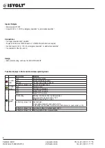
Inputs / Outputs

• dimmer outputs 700W
• 2 inputs 0-10V or 1-10V for „emergency operation“ or „stand-alone operation“

Connections

• 1 voltage connection 230V, 45-65Hz
• 2 outputs 0-230V, max. 700W/VA each or 1x1400W/VA (both channels coupled)
• 2 control inputs 0-10V or 1-10V for „emergency operation“ or „stand-alone operation“
• 1 connection for DALI (D+ and D-)

Design

• black plastic housing, can be put on 35mm DIN rail 6 HP

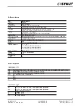
Function displays in DALI and stand-alone operating mode

LED status 

Meaning

1 x LED

(red)

OFF 

No operating voltage 

ON 

Operating voltage, no errors 

flashing 

Too high mains voltage (>400Vs) 

3x fl break 1.5s

No valid parameters found 

1 x LED

(yellow)

OFF 

No DALI signal

ON 

DALI signal is detected

2 x LED

(green)

OFF 

Output “OFF”, no errors

ON

Output “ON”, no errors

1Hz flashing

Warning / shutdown at too high temperatures: 

Communication processor: 65°C / 75°C 

MOSFET housing: 95°C / 105°C 

1x fl break 1.5s

Overload alert: 

1. Exceeding maximum peak current (>15A)

2. Reaching the limit values for power loss (>8W/channel) or peak current (>10A)

2x fl break 1.5s

Alert after shutdown at voltage peaks >450V 

3x fl break 1.5s

Communication to dim processor failed

Summary of Contents for ISYGLT 80026504

Page 1: ...GmbH www seebacher de Phone 49 0 80 41 77 77 6 Marktstrasse 57 83646 Bad Tölz info seebacher de Fax 49 0 80 41 77 77 2 1 Technical Data Instruction Manual UD 700 X2 DALI Article no 80026504 DALI Universal Dimmer ...

Page 2: ...be handed over to the device operator The operator will store the documents so that they can be made available if necessary 1 2 Symbols used Observe the following safety and other instructions in the manual Handling instruction The hand indicates that you should carry out an act Danger Immediate danger to life Attention General notes useful information and special features Directory of Content 1 N...

Page 3: ...errors 2 Safety instructions Observe the following general safety instructions when installing and commissioning the device Assembly and installation of the ISYGLT module may only be carried out by a qualified electrician Other activities in connection with the ISYGLT module such as assembly and installation of system com ponents with tested standard plug connections as well as operation and confi...

Page 4: ... screws Assembly site The product can be installed in any position in a casing to be deter mined by the electrician distribution box switch cabinet Observe maximum ambient temperature Assembly steps Read completely before assembly Mount the device in a suitable casing Make the electrical connections according to the wiring diagram Configure the DIP switches according to your requirements Only afte...

Page 5: ...ready pre defined at the factory such as dimming curves minimum and maximum limits can still be changed and optimized by the user himself For ISYGLT users the functions can be configured as usual in the ProgramDe signer A free software tool is available for the DALI or stand alone application By means of a USB or RS 485 data connection the dimmer can be optimized by parameters and internal data su...

Page 6: ...n displays in DALI and stand alone operating mode LED status Meaning 1 x LED red OFF No operating voltage ON Operating voltage no errors flashing Too high mains voltage 400Vs 3x flashing break 1 5s No valid parameters found 1 x LED yellow OFF No DALI signal ON DALI signal is detected 2 x LED green OFF Output OFF no errors ON Output ON no errors 1Hz flashing Warning shutdown at too high temperature...

Page 7: ...mming channel 1 or total Dimming channel 2 Reserve Reserve Reserve Reserve Channel 1 2 separately DIP switch stand alone operation 1 2 3 4 5 6 7 8 O N Mode U inputs 1 10V Channel 1 2 coupled 1 button dimmer Reserve U inputs 0 10V Channel 1 2 separately Analog 0 1 10V Reserve 1 2 3 4 5 6 7 8 O N U inputs 1 10V U inputs 0 10V C A B D C A B D Dimming channel 1 or total Dimming channel 2 ...

Page 8: ...n dimmer Control by means of standard buttons on the terminals UE1 and UE2 against GND Short press On Off long press dimming Analog 0 1 10V Control analog In this position the DIP switches 3 are enabled for selection 0 10V or 1 10V Operation mode setting when using DALI and stand alone mode with DIP switches A to D DIP A DIP B Operation mode OFF OFF Automatic change of operation mode the start val...

Page 9: ...mensions WxHxD 106x90x59mm DIN rail mounting 6 HP Weight 300g Connection Screw terminals 1 5mm pluggable Operating temperature 10 C to 45 C at 50 C max 60 connectable power at 55 C max 50 connectable power at 60 C max 30 connectable power Storage temperature 25 C to 70 C Humidity 0 85 r h not condensing Protection type IP30 Protection class I CE mark yes 10 1 Pin assignment 7 pole connector left G...

Page 10: ...Seebacher GmbH www seebacher de Phone 49 0 80 41 77 77 6 Marktstrasse 57 83646 Bad Tölz info seebacher de Fax 49 0 80 41 77 77 2 10 View ...

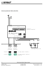
Page 11: ...nsformer dimmable ECG high voltage halogen optional external voltage control channel 1 channel 2 leading edge trailing edge Suited for trailing or leading edge trailing or leading edge max 700W max 700W Sample controlled by DALI 2x700W 0 1 10V 0 1 10V 0V DALI DALI N PE D1 D2 Art Nr RLC max 2x700VA UD 700 X2 DALI 1 2 3 4 5 6 7 8 1 2 3 4 5 6 7 8 OFF ON 80026504 L N D D LD1 LD2 N UE1 UE2 GND 10V e g ...

Page 12: ...3 4 5 6 7 8 1 2 3 4 5 6 7 8 OFF ON 80026504 L N D D LD1 LD2 N UE1 UE2 GND 10V DALI DALI N channel 1 0 1 10V 0V Sample controlled by DALI 1x1400W B6A N PE 1 optional external voltage control e g emergency function leading edge trailing edge Suited for trailing or leading edge trailing or leading edge N PE low voltage magnetic transformer low voltage electronic transformer dimmable ECG high voltage ...

Page 13: ...DIP switches please use the datasheet Sample 1 10V and 1 button dimming PE D1 D2 Art Nr RLC max 2x700VA UD 700 X2 DALI 1 2 3 4 5 6 7 8 1 2 3 4 5 6 7 8 OFF ON 80026504 L N D D LD1 LD2 N UE1 UE2 GND 10V N max 700W max 700W B6A N PE 1 leading edge trailing edge Suited for trailing or leading edge trailing or leading edge trailing or leading edge N PE N PE low voltage magnetic transformer low voltage ...

Page 14: ...0 X2 DALI 1 2 3 4 5 6 7 8 1 2 3 4 5 6 7 8 OFF ON 80026504 L N D D LD1 LD2 N UE1 UE2 GND 10V Sample Potentiometer 10kOhm A E S A E S option potentiometer 10kOhm max 700W max 700W N PE N B6A N PE 1 DIP switches please use the datasheet leading edge trailing edge Suited for trailing or leading edge trailing or leading edge trailing or leading edge 10kOhm 10kOhm low voltage magnetic transformer low vo...

Reviews: