background image

17

Glossary

Relay Circuit

A circuit in a fire alarm system that connects relay devices (e.g. fan damper relays, etc).

Remote Annunciator

A device that visually indicates, either by LCD or LEDs, the floor or zone where the alarm 
originated.

Single Stage System

A type of fire alarm system that immediately sounds all the signals throughout the building 
when an alarm is detected in any part of the system.

Silenceable Circuit

A signal circuit that can be silenced by pressing the Signal Silence button.

Supervisory Condition

Occurs when the system detects open circuits, short circuits, and grounds. A supervisory 
condition is one that would interfere with the operation of 

the fire alarm system.

Trouble Condition

Occurs when an abnormal condition such as a problem in the wiring, battery or power circuits 
exists in the fire alarm system.

Trouble Flash Rate

20 flashes per minute is the rate at which an LED will flash to indicate a trouble condition.

Two Stage System

A type of fire alarm system that causes an alert signal to sound when an alarm is detected in 
any part of the system. An alert signal advises designated persons of a fire emergency. If the 
alert signal is not acknowledged within five minutes of its initiation, an alarm signal will 
automatically sound throughout the building.

Walk Test

A test performed by a technician to ensure that each detection device is connected to the 
panel and working properly.

Zones

A fire alarm protected area that consists of at least one circuit. The terms “circuit” and “zone” 
are often used interchangeably in the fire alarm industry.

Summary of Contents for MR-2300 series

Page 1: ...User Guide LT 953SEC Rev 1 January 2017 MR 2300 Series LED Fire Alarm Control Panel...

Page 2: ......

Page 3: ...perty and Building Safety Circuit Indicators 11 3 2 4 Trouble only Circuit Indicators 11 3 2 5 Signal Circuit Indicators 12 4 0 Main Display Buttons 13 4 1 System Reset Button 13 4 2 Signal Silence Bu...

Page 4: ...hat the buttons on the main display do Refer to the Glossary on page 16 for an explanation of commonly used terms in this manual 1 2 Technical Support For all technical support inquiries please contac...

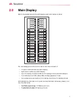
Page 5: ...be amber red or green and may illuminate continuously steady or at one of two flash rates Fast flash supervisory 120 flashes per minute Trouble flash trouble 20 flashes per minute WALK TEST REMOTE TR...

Page 6: ...6 Main Display 2 1 Paper labels for buttons and indicators Each display is supplied with laser printable labels These labels slide into the plastic label templates on the panel...

Page 7: ...n on until the system is reset The amber Common Supervisory LED illuminates at the fast flash rate when there is a supervisory alarm in the fire alarm system For non latching supervisory alarms the Su...

Page 8: ...pushed a General Alarm Initiating circuit is activated or the Auto General Alarm timer times out Once the General Alarm LED has turned on it will stay active until the panel is reset The amber Walk Te...

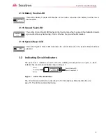
Page 9: ...uit Zone Disconnect Buttons on page 15 The LEDs are described below The amber Battery Trouble LED flashes at the trouble rate when the battery is either low or disconnected The amber Ground Fault LED...

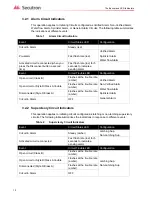
Page 10: ...onnect button a second time Fast flash rate red for 5 seconds to indicate a pending alarm Event Circuit Trouble LED Configuration Open circuit Class B Flashes at the trouble rate amber Verified Alarm...

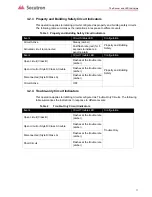
Page 11: ...rcuit Active Steady amber Property and Building Safety Activated circuit reconnected Fast flash rate red for 5 seconds to indicate a pending alarm Event Circuit Trouble LED Configuration Open circuit...

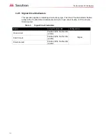
Page 12: ...cator flashes amber at the Trouble Rate to indicate short circuit or open circuit trouble or if the circuit is Disconnected Table 5 Signal Circuit Indicators Event Circuit Trouble LED Configuration Op...

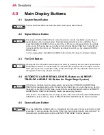
Page 13: ...the fire alarm signals without transmitting an alarm to the central station To cancel the fire drill press the button again If the fire alarm system goes into a real alarm while you are performing a f...

Page 14: ...hat all LEDs in the main display are working If you hold the Lamp Test button for more than ten seconds the Trouble LED will illuminate If the Panel is configured as a two stage system press the ALM S...

Page 15: ...ctive latching initiating circuit such as alarms water flow alarm sprinkler alarm general alarm and latching supervisory does not affect its status until the panel is reset Disconnecting active non la...

Page 16: ...a general alarm where all signals in the building will sound Indicating Circuit A circuit in a fire alarm system that is connected to audible or visual signalling devices Initiating Circuit A circuit...

Page 17: ...m Trouble Condition Occurs when an abnormal condition such as a problem in the wiring battery or power circuits exists in the fire alarm system Trouble Flash Rate 20 flashes per minute is the rate at...

Page 18: ......

Page 19: ......

Page 20: ...Tel 888 732 8876 TECHNICAL SUPPORT North America Tel 905 695 3545 International Tel 905 695 3545 Secutron 2017 Printed in Canada Subject to changewithout priornotice www secutron com CANADA Main Offic...

Reviews: