Securitytec PTZ10EXPRO Instruction Manual Download Page 17


17 

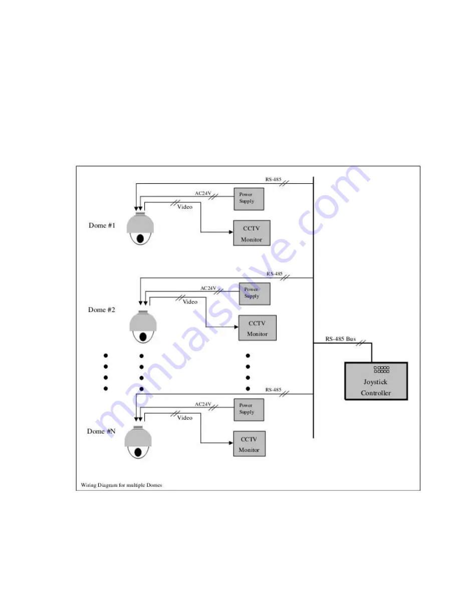
3.2 Connecting Multiple Domes   

 
When connecting multiple domes together, the user has the option to connect video and control 
terminals to a video matrix switcher or a DVR multiplexer creating an integrated system.   

AC24V

: Power supply Primary220V/110V/60H

input to AC 24V output. 

RS-485 Bus

: Control signal output from joystick controller, connected in a bus configuration to 

the RS485 communication terminals of the control cable for each dome.   

Video

:  Signal output from the dome camera  connected to a monitor, DVR, or video matrix. 

Take into consideration impedance matching and or termination.


Summary of Contents for PTZ10EXPRO

Page 1: ...High Speed Micro Dome Camera Instruction Manual English Version Indoor Version Outdoor Version Please read this manual thoroughly before use or installation and keep it handy for future reference...

Page 2: ...wer to the dome before attempting any operations or adjustments inside the dome cover to avoid potential damage to the mechanism 3 Inside the dome cover there are precision optical and electrical devi...

Page 3: ...MAY CAUSE HARMFUL INTERFERENCE TO RADIO COMMUNICATIONS OPERATION OF THIS EQUIPMENT IN A RESIDENTIAL AREA IS LIKELY TO CAUSE HARMFUL INTERFERENCE IN WHICH CASE THE USER WILL BE REQUIRED TO CORRECT THE...

Page 4: ...ay when liquid traces are present or the presence of loose objects is evident or if the device does not function properly or has received sever impact or has been dropped accidentally 13 Indoor dome i...

Page 5: ...ting Multiple Domes 18 4 Chapter 4 Quick Start Operation Guide 4 1 Connecting power to the dome 19 4 2 Setting joystick protocol and baud rate 19 4 3 Start testing 19 4 4 Complete the test 19 4 5 Dire...

Page 6: ...protocol of the controller only on power up Continuous Pan 360 degree rotation slip ring 90 degree Tilt action plus 2 degree angle adjustment the view angle can be 90 or 92 degrees Pan speed in manual...

Page 7: ...play User can define and display the name and position of the camera which differs between different models of installed cameras Resume automatic operation after initial self test of the dome as well...

Page 8: ...ceiling bracket 6 conductor Control Power Video harness 1 24VAC transformer 1500 mA 1 Wall bracket 1 Suspend bracket 4 1 Instruction manual 1 Figure 1 Illustrates the upper layer of the packing materi...

Page 9: ...r needs to be removed in order to reach the dip switch settings of the dome for proper addressing and selection of the communication protocol baud rate Step 1 Restrict the movement of the dome mechani...

Page 10: ...ss protocol and baud rate for each dome device Note The illustration shows the two Dip Switches The switch on the left 8 position is for the dome address while the switch on the right is for the proto...

Page 11: ...FF OFF OFF OFF 8 OFF OFF OFF ON OFF OFF OFF OFF 9 ON OFF OFF ON OFF OFF OFF OFF 10 OFF ON OFF ON OFF OFF OFF OFF 11 ON ON OFF ON OFF OFF OFF OFF 12 OFF OFF ON ON OFF OFF OFF OFF 13 ON OFF ON ON OFF OF...

Page 12: ...in Fig 14 Fig 13 Fig 14 Step 2 Affix the wall bracket to the wall as illustrated in Figure 15 verifying that the surface you are attaching to can support the weight of the dome using either expanding...

Page 13: ...f the wiring harness protruding out of the bracket to the mating connector on the dome unit Observe proper orientation of the connectors as illustrated Step 6 Push the dome into the bracket and align...

Page 14: ...mall click is felt indicating the beginning of the threads Step 2 Slowly start rotating the bottom part clear acrylic in a clockwise direction without forcing the threads as illustrated in Figure 18 I...

Page 15: ...s it may be a useful future reference Figure 20 is the illustration of the wiring diagram for the electrical connections to the dome unit Fig 20 Figure 21 illustrates the wiring harness included with...

Page 16: ...times please read the installation instructions carefully and become familiar with the electrical connections and setup options Incorrect wiring may result to permanent damage of the equipment 12V 12V...

Page 17: ...an integrated system AC24V Power supply Primary220V 110V 60HZ input to AC 24V output RS 485 Bus Control signal output from joystick controller connected in a bus configuration to the RS485 communicati...

Page 18: ...ud rate should be set identical with that of the dome device 4 3 Start testing When all of the above settings are completed you can start testing the dome functionality 1 Direction control test of dom...

Page 19: ...an Scan between two user preset points You can operate the Tilt and Zoom controls at the same time without interrupting the Auto Scan Motion Set Start Pan Position 52 SHOT ON Set End Pan Position 53 S...

Page 20: ...CK 2 minute 97 SHOT ACK 4 minute 98 SHOT ACK 8 minute 99 SHOT ACK 10 minutes To disable the return to Home Position function press 100 SHOT ON Intelligent three dimension tour scan setting If a user w...

Page 21: ...d sub menus can be accessed directly from the keyboard by entering 57 SHOT ACK or 57 PRESET depending the model and type of the selected keyboard controller Main Camera Menu Cam Title Sub Menu Whitek...

Page 22: ...he joystick to the Left or Right position you can change the value of your selection or access the submenu for the selected option 3 Press the button IRIS OPEN on the keyboard controller to confirm yo...

Page 23: ...d tree of the OSD menu and sub menus is illustrated below Note Due to space limitations not all screen shots are displayed on this page Additional information is displayed in 5 2 1 5 2 2 5 2 3 5 2 4 5...

Page 24: ...ect a preset position from 1 165 2 Move the PTZ to desired location Iris Close to set it On Screen message displays Stored for verification 3 User can recall the selected preset for position validatio...

Page 25: ...Preshot Based on the displayed selected preset position on line 1 of this menu the dome will respond upon moving the joystick to the Right position and position itself to the corresponding coordinates...

Page 26: ...l appear on the screen Move the joystick right to select a sector position 1 8 Press IRIS CLOSE button to return to previous menu 5 2 2 2 2 Name _ _ _ _ _ _ _ _ User can subsequently name the sector b...

Page 27: ...S CLOSE button to set the starting pan position coordinates and return to the previous menu level 5 2 2 2 4 Pan End POSITION Move the joystick up or down to the desired selection Move the joystick rig...

Page 28: ...End coordinates for the selected sector Press IRIS CLOSE button to set the Tilt End position coordinates and return to the previous menu level 5 2 2 2 7 Name Display Move the joystick up or down to t...

Page 29: ...Up Message Move the joystick up or down to the desired selection Move the joystick Left or Right to select ON or OFF Based on your selection the startup message see below will be displayed on Power U...

Page 30: ...e the joystick Left or Right to choose ON or OFF This allows the user to change the direction the pan motor It is useful under certain conditions based on the physical installation of the PTZ Example...

Page 31: ...tions Press IRIS CLOSE button to exit and return to the previous menu level 5 2 3 2 1 Default Function This defines the behavior of the dome to respond to a preset or a vector as the default position...

Page 32: ...5 2 3 2 4 Operation Move the joystick up or down to the desired selection Move the joystick Left or Right to make selection ON PTZ will return to default position OFF PTZ will remain in last position...

Page 33: ...posure camera control PTZ Auto Exposure The camera adjusts the brightness automatically while monitoring the screen continuously OFF Manual Operation user must adjust exposure manually Z Camera will a...

Page 34: ...35 The following section describes Diagnostic options for the dome functions...

Page 35: ...turn to the previous menu 5 2 4 2 Restore Default Setting Move the joystick up or down to the desired selection Move the joystick Left or Right to make selection This selection allows the user to rest...

Page 36: ...Camera Options Move the joystick up or down to the desired selection Move the joystick Left or Right to make selection Different options are possible based on the function you selected including sub...

Page 37: ...or right again under the desired numeral and press IRIS OPEN button again to select the desired number 0 9 Press IRIS OPEN button again to confirm the selection Press IRIS CLOSE button to finalize you...

Page 38: ...OFF ON Sub Menu D ZOOM LIMIT SETUP LIMIT X 2 10 END DISP ZOOM MAG ON OFF ZOOM POS INIT ON OFF ON Sub Menu ZOOM INIT POS SETUP X 1 10 END LENS INIT END EXPOSURE EXPOSURE SETUP Sub Menu BRIGHTNESS IRIS...

Page 39: ...2 10 END DISP ZOOM MAG ON OFF END EXPOSURE EXPOSURE SETUP BRIGHTNESS 1 100 IRIS AUTO MANUAL MANUAL IRIS MANUAL SETUP IRIS VAL 1 100 END SHUTTER A FLK _ _ _ MANUAL MANUAL SHUTTER MANUAL SETUP SHUTTER...

Page 40: ...IVACY ON OFF ON PRIVACY SETUP GROUP SEL GROUP 1 8 AREA SEL 1 4 AREA MODE ON OFF MASK TONE 1 100 TOP 1 200 BOTTOM 1 200 LEFT 1 200 RIGHT 1 200 END DAY NIGHT AUTO 1 2 COLOR B W SYNC INT EXT COMM A DJ CO...

Page 41: ...A TITLE SETUP Move the joystick up or down to the desired selection Move the joystick Left or Right to select desired character 0 9 or A Z Press IRIS OPEN button to confirm selection and move to the n...

Page 42: ...a clear image of the subject even with bright backlight Move the joystick Left or Right to choose There are several settings available HIGH Gain increased from 6dB up to 34dB MIDDLE Gain increased fr...

Page 43: ...gital Zoom can be selected from OFF 2X 10X Additional options are available such initial position and magnification including Lens Initialization NOTE It is recommended that you set digital zoom befor...

Page 44: ...thers features for specific preset settings There are a total of 8 positions that are user configurable in great detail Move the joystick up or down to preset save to save your selection Move the joys...

Page 45: ...can reset the camera to original factory settings Move the joystick up or down to the desired selection Press IRIS CLOSE button to reset the camera The screen will turn black momentarily and the came...

Page 46: ...ing speed Enable system default guard tour 52 Enable Auto Pan scanning Set Start Pan Position 53 System hold Set End Pan Position 55 Background Light Compensation On Off 58 Digital Zoom On Off 59 Focu...

Page 47: ...uto Flip Manual pan speed 0 1 240 Manual tilt speed 0 1 120 s Speed of preset 300 s Preset Accuracy 0 10 s Preset positins 128 Tours Guard Tour 6 Programmable Communication protocol PELCO D P Communic...

Page 48: ...splay After self test the menu can be displayed only when there is Video image on the monitor Fault of OSD control board Replace OSD board 4 Distorted Characters or video image Interference caused by...

Page 49: ...n instructions Improper connection of control cable polarity Verify the polarity of the RS485 connection as per the instruction manual 10 Intermittent control of dome device Maximum Communication cabl...

Page 50: ...he dome flips rotates the camera starts moving upward as long as the tilt control is kept in the down position Once the control is released the tilt control returns to its normal operational mode The...

Page 51: ...dome camera Depending the model SHUTTER LIMIT Setting used to define the maximum exposure time for the Open Shutter setting The values for the setting range from 1 2 to 1 60 The default setting is 1...

Page 52: ...53 Note Specifications subject to change without notice All rights reserved...

Page 53: ...54 Rev L5P 02 090213...

Page 54: ......

Reviews: