background image

HD-CVI Plastic Housing

Step 1

Please take the installation position map from the accessories bag, and then 

paste it on the ceiling or the wall according to your monitor area requirements. 

Draw and then drill three holes in the installation surface and then insert three 

expansion bolts in the holes. Secure these three bolts firmly.

Step 2

Turn counter clockwise to remove the decoration ring. Please drill a “cable exit 

hole” in the surface according to the installation position map if you want to 

draw out the cable from the top of the installation surface. You need to draw out 

the cable from the cable channel side port of the pedestal if you want to draw 

out the cable from the side port of the cable channel. Adjust the device instal-

lation pedestal to the proper position and then draw the cable through the ca-

ble exit. Line up the three screw holes in the installation position. Put the three 

self-tapping screws in the three plastic expansion bolts firmly. Now the dome 

camera is secure in the installation surface.

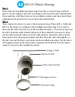
3.2

Ceiling or Wall

Expansion Bolt

Dome Camera Body

ST3 Self-tapping Screws

Decoration Ring

Summary of Contents for CVIOB-TP1IRE

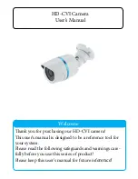
Page 1: ...purchasing our HD CVI camera This user s manual is designed to be a reference tool for your system Please read the following safeguards and warnings care fully before you use this series of product Pl...

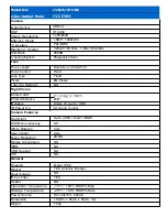
Page 2: ...rared LED Infrared Distance IR Status 20M Under 10 Lux by CDS IR Power On CDS Auto Control Camera Features Day Night Auto ICR I Color I B W NO White Balance Auto Gain Control Auto Noise Reduction 2D N...

Page 3: ...rage and installation 3 Installation Do not apply power to the camera before completing installation Please install the proper power cut off device during the installation connection Always follow the...

Page 4: ...ase open the package and check all the components that are included Contact your local retailer ASAP if something is broken in your package 7 Daily Maintenance Please shut down the device and then unp...

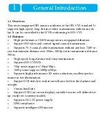
Page 5: ...ssion without any loss 720P se ries transmission distance over 500m 1080p series transmission distance 300m High speed long distance real time transmission Support HD CVI HD 720p series supports 720p...

Page 6: ...ing trouble finding the dimensions you can find the measurements by using a caliper or a ruler To find the circumference of the bottom of the camera use the fol lowing formula Diameter of circle x 3 1...

Page 7: ...HD CVI Plastic Housing 2 Lens Dome Body Decoration Ring...

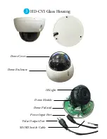
Page 8: ...HD CVI Glass Housing 3 Dome Cover Dome Enclosure IR Light Dome Module Dome Pedestal Power Input Port Video Output Port SD HD Switch Cable...

Page 9: ...mera is usually installed on a ceiling Although It could also be in stalled on a wall For the side exit cable installation please make sure the side exit cable direction is the same as shown in the in...

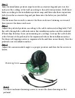
Page 10: ...ep 3 Adjust the pedestal position according to the cable exit move ceiling side Pull the cable through the cable side exit at the installation surface and the pedestal Please skip this step if you are...

Page 11: ...nstallation position map if you want to draw out the cable from the top of the installation surface You need to draw out the cable from the cable channel side port of the pedestal if you want to draw...

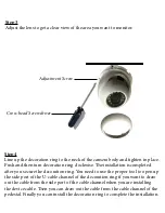
Page 12: ...fter you secure the decoration ring You need to use the proper tool to open up the side port of the U cable channel of the decoration ring if you want to draw out the cable from the side port of the c...

Page 13: ...n the pan base to the pedestal to loosen or secure firmly Adjust and rotate base and the dome body to get the lens to the proper monitor angle HD CVI Metal Housing 3 3 B1 Pedestal B2 Pan Base B3 Rotat...

Page 14: ...r mod el If you are having trouble finding the dimensions you can find the measurements by using a caliper or try your best using a ruler To find the circumference of the bottom of the camera use the...

Page 15: ...n bolt if you want to install in cement wall make sure the installation holes of the expansion bolts are the same as the bracket and then you can install the bracket If you want to install in a wood s...

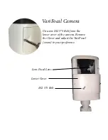
Page 16: ...VariFocal Camera Lower Cover Lens Focal Lens M2 5 5 Bolt Unscrew M2 5 5 Bolt from the lower cover of the camera Remove the Cover and adjust the VariFocal zoom to your preference...

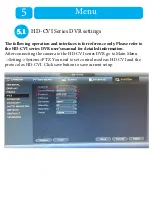
Page 17: ...eference only Please refer to the HD CVI series DVR user s manual for detailed information After connecting the camera to the HD CVI series DVR go to Main Menu Setting System PTZ You need to set contr...

Page 18: ...ation Click up down but ton to view all the items on the left pane of the following list Click left right button to set the corresponding values on the right pane of the following list If there is cli...

Reviews: