Rev. 8/00
Page- 2
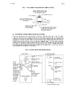
FIG. 1: COLLAPSING THE BLIND NUTS (METAL DOOR)
DOOR
TOOL
CAP SCREW
BLIND NUT
DRILL 3/8" (9.5MM) HOLE
NUT AS SHOWN
PRESS IN BLIND
COLLAPSES WHEN CAP SCREW
TURNED WITH ALLEN WRENCH
WHILE TOOL HELD FAST
WITH BOX WRENCH
WHILE TURNING WITH ALLEN
WRENCH, PRESS IN TO KEEP
NUT SEATED IN DOOR
HOLD WITH WRENCH OR
CAP SCREW
VISE GRIP WHILE TURNING
-1/4-20 X 1"
FLAT WASHER
KNURL
2.5 ELECTRICAL CONNECTIONS WITHIN PLASTIC BASE
These connections must be made before the handle is attached to the base. First, the cable
connector must be correctly routed across the circuit board and plugged into the corresponding
connector on the board. See Figure 2 and note the correct cable routing and orientation of
plugging it in. Second, note that there is a free brown wire with a toothed ring terminal on its end
soldered into the circuit board. This is called the “
antenna wire
”. It must make conductive
contact with the aluminum handle to allow a person’s touch to be detected. Figure 2 also shows
the handle. A machine screw is “parked” in the antenna hole in the handle.
Remove this screw,
run it through the ring terminal and then replace it in the same hole
. You are now ready for
final installation of the handle on to the base.
FIG. 2: PLASTIC BASE AND HANDLE DETAIL
PLASTIC BASE
CIRCUIT BOARD
ANTENNA WIRE
WITH RING
TERMINAL
BACKUP
SWITCH
POT
ROUTE
CABLE
CONNECTOR
AND PLUG
IN AS SHOWN,
POSITION
FEMALE
CONNECTOR
TO RIGHT OF
CABLE (NOTE
RED MARKS
ON CONNEC-
TOR FACE
TOWARDS
EDGE OF
CIRCUIT
BOARD)
ALUMINUM HANDLE
MOUNTING
HOLE TO BASE
MOUNTING
HOLE TO BASE
HOLE TO VIEW
LED
POT ACCESS
HOLE
ANTENNA WIRE
MOUNTING
HOLE
PLAQUE MOUNTING HOLE
LED
HANDLE MOUNTING
HOLE
MOUNTING HOLE
TO DOOR
CABLE ENTERS
DOOR OVER NOTCH
Summary of Contents for TSH
Page 8: ...Rev 8 00 Page 8...


