Secure Power Ltd
User Manual
…………………………………………………………………………………………………………
23
Opto-coupler input specifications (used for remote shutdown):
Parameter
Value
Reverse voltage (V
R
)
6 V d.c.
Forward input voltage
30 V d.c. max., 5 to 12 V d.c. typical
Forward current
80 mA max., 16 mA typical
Pulse forward current (I
FP
)
1 A (100 µs pulse, 100 pps)
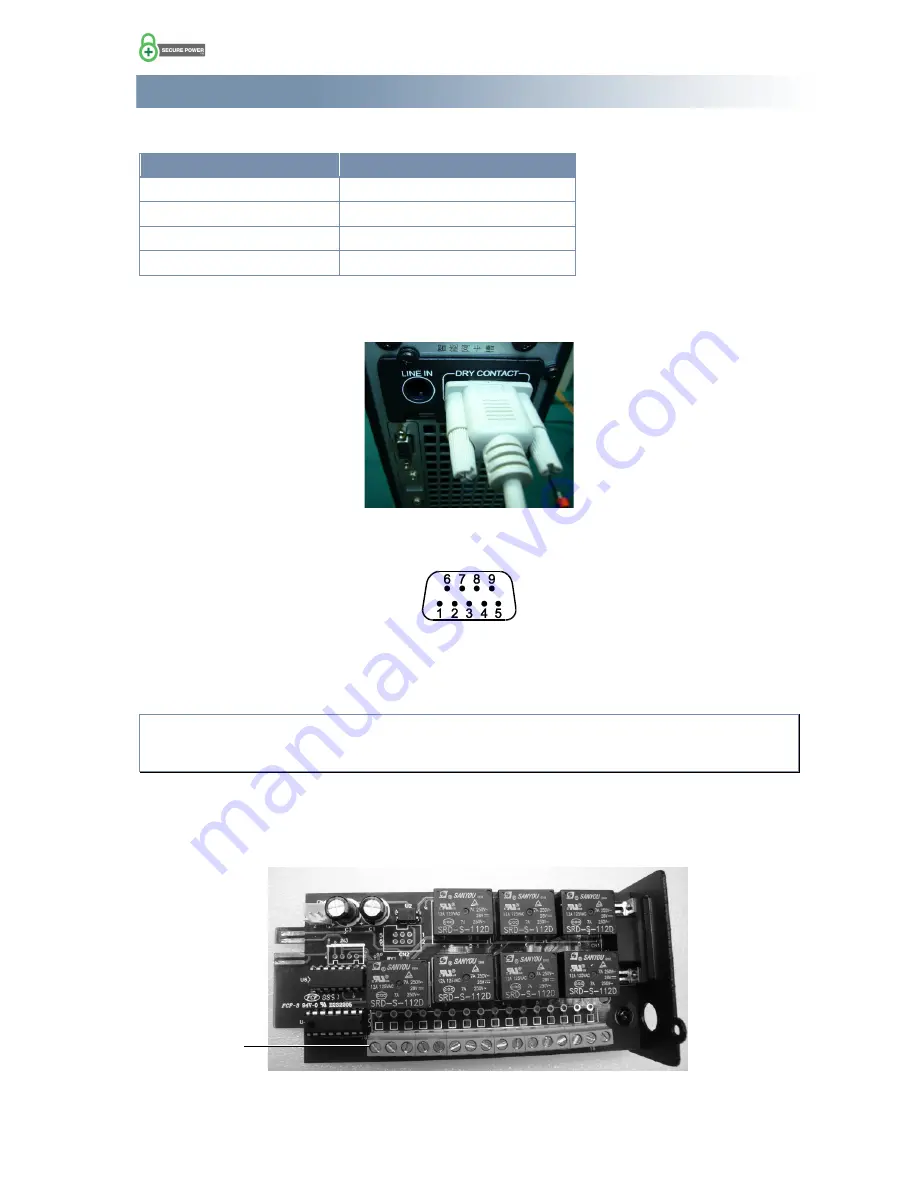
To use the 9 pin D-type connector:
1. On the UPS, plug your signal cable into the D-type connector and secure with the screw locks.
2. On the other end of the cable, wire the signals as required in your system (see the connection table
on the previous page and the pin out information below).
To connect to the 16-way terminal block:
Note:
There is limited space between the terminal block and the edge of the mounting slot. It is
therefore advisable to use fine wire (0.5 mm
2
max.) to make it easier to bend and dress the wires out of
the way.
1. Using a PH2 Phillips screwdriver, remove the two screws holding the relay card in place, and remove
the card.
2. Feed your signal wires through the hole in the cover plate and wire to the appropriate terminals (see
the connection table on the previous page).
3. Refit the card and secure it in place with the two screws.
D-type socket pin-outs looking
at the socket on the UPS
Terminal 1


