SBC-C20
SBC-C20 User Manual - Rev. First Edition: 1.0 - Last Edition: 1.0 - Author: A.R. - Reviewed by C.M. -Copyright © 2020 SECO S.p.A.
30
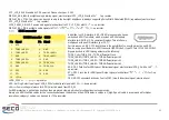
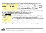
W_DISABLE1#: M.2 module disable output signal #1, VDD_3P3V active low output
UIM_RESET: Reset signal line, sent from M.2 WWAN card to the UIM module.
UIM_DATA: Bidirectional Data line between M.2 WWAN card and UIM module.
UIM_CLK: Clock line, output from M.2 WWAN card to the UIM module.
UIM_PWR: Power line for UIM module.
SIM_DETECT: This signal can be forced to VDD_3P3V (through a 10k
Ω
pull-up resistor) by
using a dedicated jumper, JP3. When JP3 is not placed, this pin will be floating.
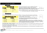
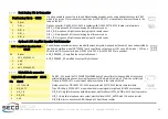
microSIM Card Slot
Interfaced to the M.2 slot CN26, as already told in paragraph 3.3.10, there is a
microSIM Card Slot, to be used in conjunction with M.2 Socket 2 Key B modems.
Here it is possible to insert the microSIM card provided by any telecommunication
operator for the connection to their network.
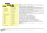
The socket is type MOLEX. p/n 78800-0001or equivalent, with the pinout shown
in the table on the left. The signals are already described in par 3.3.10.
59
---
60
---
61
---
62
---
63
---
64
---
65
---
66
SIM_DETECT
67
---
68
---
69
---
70
VDD_3P3V
71
GND
72
VDD_3P3V
73
GND
74
VDD_3P3V
75
----
microSIM Card Slot CN27
Pin Signal
Pin Signal
1
UIM_PWR
5
GND
2
UIM_RST#
6
---
3
UIM_CLK
7
UIM_DATA
4
---
8
---


