


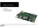


SBC-C20
SBC-C20 User Manual - Rev. First Edition: 1.0 - Last Edition: 1.0 - Author: A.R. - Reviewed by C.M. -Copyright © 2020 SECO S.p.A.
20
3.1
Introduction
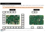
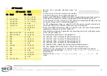
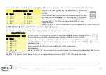
On SBC-C20 board, there are several connectors located on the upper plane. Standard connectors are placed on the same side of PCB, so that it is possible to
place them on a panel of an eventual enclosure.
Please be aware that, depending on the configuration purchased, the appearance of the board can be significantly different from the following pictures.
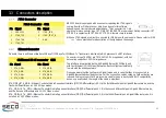
microSIM
Card Slot
JTAG
eDP
USB
Recovery
LED Driver
BOTTOM SIDE
GPIO
CSI
Camera
USB 3.0
GbEthernet
Dual
Analog MIC
In
CAN Bus
Digital MIC In
RTC battery
SPI
TRRS
Audio jack
RS-232
Power In
microSD
slot
LVDS +
backlight
Line Out,
HP Out
Reset
Debug
UART
Dual USB
2.0 Type-A
HDMI
I2C Touch
Screen
USB
header
M.2 Socket2
Key B
Power
On/Off
10W
Amplified
Speaker
LCD &
Backlight
Power Sel
JP1,3,4
TOP SIDE


