
®
1200-lb Electromagnetic Lock
2
SECO-LARM
®
U.S.A., Inc
Specifications:
E-941SA-1K2PQ
E-941SA-1K2PDQ
E-941DA-1K2PQ
Door Type
Single Door
Double Door
Magnet Size
10
1
/
2
”x1
19
/
32
”x2
5
/
8
”
(267x40x67 mm)
21”x1
19
/
32
”x2
5
/
8
”
(534x40x67 mm)
Armature Size
7
1
/
4
”x
5
/
8
”x2
3
/
8
”
(185x16x61 mm)
7
1
/
4
”x
5
/
8
”x2
3
/
8
” x 2
(185x16x61 mm) x 2
Status Sensor
Relay, 1A@12VDC
1
Status LED (2-color)
Green (locked), Red (unlocked)
1
Timer
2
n/a
0, 2.5, 5, 9 seconds
n/a
Weight
11-lb (5.0kg)
22.5-lb (10kg)
Holding Force
1200-lb (545kg)
1
Power
12VDC/24VDC
Current Drain
475mA@12VDC
1
/ 250mA@24VDC
1
Voltage Tolerance
±10%
Housing
Aluminum
Temperature
14°~131° F (-10°~°55 C)
1
On each side, for double door models
2
E-941SA-1K2PDQ only
Installation:
A.
Drill holes for the mounting plate and armature
plate (see fig. 1 and 2) by doing the following:
1.
Fold the mounting template along the dotted
line.
2.
Close the door. Find a mounting location on
the door frame near the upper free-moving
corner of the door, as close to the corner of
the door frame as possible.
3.
Place the template against the door and
frame.
4.
Drill two holes in the door frame and three
holes in the door as indicated on the
template.
NOTE:
A filler plate or an L-bracket or Z-bracket
(optional) may be required for the electromagnet,
depending on the door frame. See fig. 1.
B.
Mount the armature plate to the door using at
least two steel washers and one rubber washer
(fig. 2):
NOTE:
Actual installation varies according to door style.
1.
Put one rubber washer between two steel
washers, and place them over the armature
screw between the armature plate and the
door. This will allow the armature plate to
pivot slightly around the armature screw in
order to compensate for door misalignment.
2.
Tighten the sexnut bolt enough so the
armature plate can withstand the force of
someone attempting to break down the door
while the electromagnet is engaged.
3.
Do not tighten the armature plate against the
door. The plate must be able to pivot around the
armature screw.
4.
Make sure the anti-spin guides are in the two
guidepin holes.
C.
Screw the mounting plate onto the door frame or
optional bracket:
1.
Screw the two short self-tapping screws in the
slotted holes of the mounting plate and adjust
the position of the mounting plate so that it and
the armature plate form a 90-degree angle.
2.
Once the position is correct, use the long self-
tapping screws to permanently mount the
bracket.
3.
Remove the two short screws.
D.
Drill the cable access hole.
E.
Mount the electromagnet on the door frame (fig. 1)
1.
Use the Allen wrench to screw the socket-head
mounting screws through the bottom of the
electromagnet into the mounting bracket.
F.
Connect the power leads (fig. 3)
1.
Open the electromagnet and run two power
leads from the power supply through the cable
access hole into the electromagnet.
2.
Connect the power leads to the terminal block
and close the electromagnet.
3.
Test the unit.
G.
Insert the tamper caps into the mounting screw
access holes.
NOTE:
This should be the last step, as once the tamper
caps are in place, they are difficult to remove.
ENFORCER
®
1200-lb Electromagnetic Lock
SECO-LARM
®
U.S.A., Inc
3
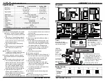
Diagrams:
Figure 1
Figure 2
Setting the timer:
Seconds
0s
3
2.5s
5s
9s
DIP swtch
position
OFF / OFF
OFF / ON
ON / OFF
ON / ON
3
Default
Relay
Voltage
Selection
Jumpers
E-941SA-1K2PDQ
Power
Supply
Status LED
3
3
Status LED:
Indicates whether
the magnetic lock
is locked or
unlocked.
Green — Locked
Red — Unlocked
Off — No power
P
.S
.
A
B
A:
For standard function, connect control
device(s) between the power supply and
electromagnetic lock positive terminals ( + ).
B:
E-941SA-PDQ only
. For timer function,
connect control device(s) between the power
supply negative terminal ( - ) and the
electromagnetic lock P.S. terminal.
NOTE
: Choose either A or B—do not connect both.
Timer DIP Switch
E-941SA-1K2PDQ only
.
Status Sensor Output
SPDT rated 1A@12VDC
Voltage Selection
24VDC
Position a jumper over
the two middle pins for
24VDC operation.
Status Sensor Output:
Monitors whether the protected door
is open or closed.
N.C. — Door is open, red LED on.
N.O. — Door closed, green LED on.
Relay — 1A@12VDC.
Figure 3
Status Sensor Output:
Connect to an alarm panel or
other monitoring device
12VDC
Magnet set for 12VDC
operation as supplied
from factory.
* Note: may require more than
one filler plate.


