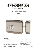
SECO-LARM Electro-Mechanical Latch
SECO-LARM U.S.A., Inc.
3
Installation:
1.
Determine the best mounting location for the strike
body and lock body. The recommended distance
between the strike body and the lock body is
3
/
16
"
(5mm) (see Fig. 2). Note the offset mounting as
shown in Fig. 1.
2.
Place the included template on the closed gate/door
and the frame. Drill four
1
/
8
" (3mm) holes for
mounting the lock body, four
1
/
8
" (3mm) holes for
mounting the strike body, a 1
1
/
4
" (32mm) hole for
the cylinder lock, and a hole to run the wires to the
lock body.
NOTE:
Template/lock's orientation varies depending
on the handedness of the door/gate.
3.
Install the key plate to the gate/door or frame with
four M3 self-tapping screws (see Fig. 3).
4.
Assemble the cylinder lock from the opposite side of
the door so that the cylinder lock's flat pin can be
inserted into the lock body.
NOTE:
The cylinder lock's flat pin and long screws
(used to secure the cylinder lock as noted
below) should be cut to the appropriate
length before they are installed.
5.
Secure the cylinder lock in place with the two long
screws (see Fig. 4).
6.
Remove the cover of the lock body by unscrewing
the two screws on the side of the lock body.
7.
Using four M5 self-tapping screws, mount the lock
body (see Fig. 5).
8.
Unscrew and remove the cover of the strike body.
9.
Using four M5 self-tapping screws, mount the strike
body to the door/gate or frame and reattach the
strike body's cover (see Fig. 6).
10.
Connect the wires (non-polarized) to an access
control system.
11.
Test the latch to ensure it is working properly.
12.
Reattach the lock body’s cover.
NOTE:
Copy keys as necessary and save one as
the master key. Replacement keys are
not available.
3
/
16
" (5mm)
Fig. 2
Fig. 6
Fig. 3
Fig. 5
Fig. 4


