15
MONITOR MENU
PROGRAMMATION MENU
By means of MONITOR MENU and acoustic signals (Buzzer) the Device highlights the fol-
lowing informations:
TEST ANOMALY SIGNAL:
LED switch-on + Buzzer.
Highlights an anomaly in executing the test by the control unit (see “DEVICE TEST” para-
graph).
ALARM SIGNAL:
LED Switch-on + Buzzer.
Informs which of the RTX 2252 memorised devices is in alarm. A short Beep corresponds
to every LED of reference switch-on.
————————————— MENU’ MONITOR —————————————
LED Reference
LED Off
LED On
1) TEST
Test = OK
Test = ERR.
2) CODE 1 CH1
No Alarm
CODE 1 CH1 Alarm
3) CODE 2 CH1
No Alarm
CODE 2 CH1 Alarm
4) CODE 3 CH1
No Alarm
CODE 3 CH1 Alarm
5) CODE 1 CH2
No Alarm
CODE 1 CH2 Alarm
6) CODE 2 CH2
No Alarm
CODE 2 CH2 Alarm
7) CODE 3 CH2
No Alarm
CODE 3 CH2 Alarm
DISCHARGED BATTERY SIGNAL:
LED Switch-on (quick Flashes) + Buzzer.
Informs which of the memorised RTX 2252 devices has discharged batteries. Every minute
two quick Buzzer Beeps are transmitted and the LED of reference switches-on.
———————————— — MENU’ MONITOR —————————————
LED Reference
LED Off
Flashing LED
1) TEST
NOT USED
NOT USED
2) CODE 1 CH1
Battery OK
Battery LOW
3) CODE 2 CH1
Battery OK
Battery LOW
4) CODE 3 CH1
Battery OK
Battery LOW
5) CODE 1 CH2
Battery OK
Battery LOW
6) CODE 2 CH2
Battery OK
Battery LOW
7) CODE 3 CH2
Battery OK
Battery LOW
As for PROGRAMMATION MENU see paragraph “Programming Keys and Indicator Leds”.
8K2/CONTACT FUNCTIONING MODE SELECTION
The RTX 2251 (Base) device selects the CH1 and CH2 relay control outputs.
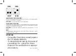
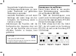
Selection is through Jumper J1 and J2:
J1 pos. 1-2 = 8K2 CH1 relay output.
J1 pos. 2-3 = NC CH1 relay output (default).
J2 pos. 1-2 = 8K2 CH2 relay output.
J2 pos. 2-3 = NC CH2 relay output (default).
Device Test:
The RTX 2251 (Base) device has a “Test” input to be used when the control unit it ‘s
coupled with is equipped with Safety Devices test function. Test is performed as follows:
the control unit must switch the signal in “Test” input from high logic level (12-24 Vac-dc
during normal functioning) to low logic level: the RTX 2251 device must respond varying
the state of the two CH1 and CH2 channels outputs to pass the test.
Control of the Selected Frequency
Before programming the RTX 2252 (Sensors) codes associated to the RTX 2251 (Base) it’s
necessary to select one of the four frequency channels available (see paragraph “Func-
tioning Frequency selection”) and it’s advisable to verify that the channel selected is free;
to do that proceed ad follow: with SET button go to PROGRAMMATION MENU; the Base
makes a scanning of the channel selected and if it’s busy the Base will signalize this with
an alternately flashing of LED MONITOR and LED MENU PROGR.. In this case choose
an other frequency ( on Base and on Sensor). If the channel selected is free, makes the
programming of the Sensor as indicated in the next paragraph.
PROGRAMMING KEYS AND INDICATOR LEDS
SEL Key:
selects the type of function to memorise, the choice is indicated by the flashing of the
LED. Repeatedly press the key to position oneself on the desired function. After 15 seconds of
activation displayed by the flashing LED, the device returns to original state.
SET Key:
- selects between Monitor Menu and Programming Menu: the Monitor Menu is automati-
cally selected after 1 minute of SEL and SET keys inactivity.
- programs the function chosen with the SEL key.
Indicator LED:
LED on: option memorised.
LED off: option not memorised.
Flashing LED: option selected.


