


7
ASSEMBLY INSTRUCTIONS
It will take two people to assemble your unit.
Set the treadmill in a cleared area and remove all packing material. Do not dispose of the material until your
assembly is completed. Note: The underside of your treadmill’s walking belt is coated with a lubricant.
During shipping, a small amount of lubricant may be transferred to the top of the walking belt or the shipping
carton. This does not affect the treadmill’s performance. If you notice any lubricant on the top of the walking
belt, simply wipe off the lubricant with a soft cloth and a mild, non abrasive cleaner.
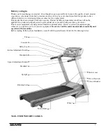
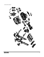
For the sake of familiarizing yourself with the parts identified in the instructions, first study the overview
drawing.
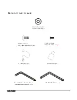
Assembly only
requires the included wrenches.
STEP 1
Remove all the components from the carton.
STEP 2
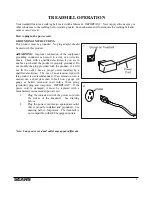
Connect the computer extension cable (37) to the lower computer cable (38).
NOTE: Ensure that the wire is safely inserted in the upright to avoid pinching the computer wire.
STEP 3
Fasten the right upright (5) into the frame base (2). Secure using three 5/16” x 15mm button head bolts (94).
Secure the back of the right upright (5) with one 5/16” curved washer (95) and one 5/16” x 15mm button head
bolt (94) using the combination wrench / screwdriver (97).
Repeat for left upright (4).
HAND TIGHTEN ONLY FOR NOW
STEP4
Connect the computer extension cable (37) to the upper computer extension cable (36) from the console support
(6).
NOTE:
Carefully insert the cables inside the console assembly, so that you do not pinch and cut the cables
when fastening the console assembly.
Install the console support assembly (6) into the right and left uprights (4,5). Secure the right upright (5) with
three 5/16” x 15mm button head bolts (94). Secure the back of the right upright (5) with one 5/16” curved
washer and one 5/16” x 15mm button head bolt (94) using the combination wrench / screwdriver (97).
Repeat for the left upright (4).
HAND TIGHTEN ONLY FOR NOW
STEP 5
Connect the upper computer extension cable (36) to the back of the console (39).
Connect the speed switch w/cable (25) to the back of the console (39).
Connect the incline switch w/cable (26) to the back of the console (39).
Connect the handpulse wire (27-1) to the back of the console (39).
Slide the console (39) on to the console support assembly (6) through the back opening of the console
(39). Secure the back of the console (39) with four M5 x15mm phillips head screws (96) and the bottom back
of the console (39) with two M5 x15mm phillips head screws (96), using the combination wrench /
screwdriver (97).
ENSURE THAT ALL NUTS AND BOLTS ARE NOW FIRMLY TIGHTEN
Summary of Contents for Free Spirit C 249 30199 0
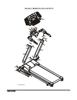
Page 9: ...8 READ UNDERSTAND AND TEST 39 ...
Page 34: ...33 ...


