


11
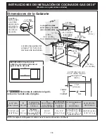
30" GAS SLIDE-IN RANGE INSTALLATION INSTRUCTIONS
(Models with Sealed Top Burners)
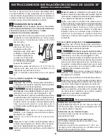
Hollow
Valve
Stem
Figure 14
Figure 15
A
B
11.2
Turn on Electrical Power and Open
Main Shutoff Gas Valve
Fig. 13
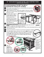
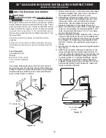
Burner Cap
Burner
Head
Fig. 10
Correct Burner Cap
Placement - Fig. 11
Incorrect Burner Cap
Placement - Fig. 12
Burner
Cap Lip
11.3
Check the Igniters
Operation of electric igniters should be checked after
range and supply line connectors have been carefully
checked for leaks and range has been connected to
electric power.
a. To check for proper lighting, push in and turn a surface
burner knob to the LITE position. You will hear the
igniter sparking.
b. The surface burner should ignite when gas is available
to the burner. Purge air from supply lines by leaving
knob in the
LITE
position until burner ignites. Each
burner should light within four (4) seconds in normal
operation after air has been purged from supply lines.
c. Visually check that burner has a flame, Once the
burner ignites, the control knob should be turned
out of the LITE position.
d. Try each surface control knob separately until all
burner valves have been checked. Each burner
location is equipped with a separate electrode.
11.4
Adjust the
"
LOW
"
Setting of Surface
Burner Valves (linear flow)
Test to verify if LOW setting should be adjusted:
a. Push in and turn control to LITE until burner ignites.
b. Push in and quickly turn knob to lowest position.
c. If burner goes out, reset control to OFF.
d. Remove the surface burner control knob.
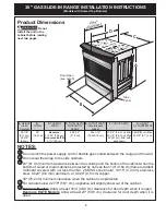
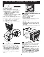
For all burner styles (except Bridge burner)
e. Insert a thin-bladed screwdriver into the hollow valve
stem and engage the slotted screw inside. Flame
size can be increased or decreased with the turn of
screw. Turn counterclockwise to increase flame size.
Turn clockwise to decrease flame size (Figure 14).
Adjust flame until you can quickly turn knob from LITE
to lowest position without extinguishing the flame. Flame
should be as small as possible without extinguishing.
NOTE:
On dual burners, the inner flame cannot be
adjusted. Adjustments are made to the outer flame only.
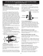
For Bridge burner style adjustment only:
e. The flame size on the rear portion of the bridge
burner can be increased or decreased by turning
screw
A
. Use screw
B
to adjust flame size of the
center portion of the Bridge Burner (Figure 15). Turn
the screw counterclockwise to increase flame size.
Turn clockwise to decrease flame size. Adjust flame
size until you can quickly turn the knob from LITE to
lowest position without extinguishing the flame.
Note: Air mixture adjustments are not required on
surface burners.
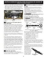
To prevent flare-ups and avoid
creation of harmful by-products, do not use the cooktop
without all burner caps properly installed to insure
proper ignition and gas flame size.
Always keep the burner caps and burner heads in
place whenever the surface burners are in use.
DO
not allow spills, food, cleaning agents or any other
material to enter the gas orifice holder openings.
Check and be sure the size of each burner cap
matches the size of the burner head. Check and be
sure that all round style burner caps are correctly in
place on round burner heads.
Check and be sure that all oval style burner caps are
correctly in place on oval burner heads (if equipped).
Check and be sure that all dual or twin style burner
caps are correctly in place on dual or twin heads (if
equipped).
On round style burners, the burner cap lip (Figure 10)
should fit snug into the center of burner head and be
level. Refer to figures 11 & 12 for correct and incorrect
burner cap placement.
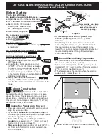
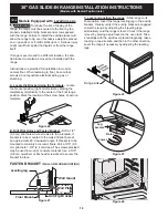
Once in place, you may check the fit by gently sliding
the burner cap from side to side (Figure 13) to be sure
it is centered and firmly seated. When the burner cap lip
makes contact inside the center of the burner head you
will be able to hear the burner cap click. Please note
that the burner cap should NOT move off the center of
the burner head when sliding from side to side.
Summary of Contents for 30" GAS SLIDE-IN RANGE
Page 44: ...44 NOTES NOTAS...


