SL-300-1D5 Series
13-21NM Marine Lanterns
Latest products and information available at
www.sealite.com
39
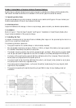
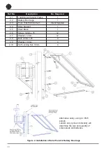
3.2 Installing the Solar Panel & Battery Box Cage
The battery box cage (Ref 2.2) and the steel support bracket (Ref 2.4) are attached to the post (Ref
2.3) using coach screws and washers (Ref 2.6, 2.7).
a. Drill the post for the steel support bracket (6 places) and install using supplied screws
IMPORTANT:
the Solar Panel must face the equator. Locate the solar panel support bracket
accordingly.
b. Drill the post for the battery box cage (6 places) on the opposite side to the solar panel and install
using supplied screws
c. Install the solar panel and frame (Ref 2.1) and the brace (Ref 2.5) to the steel support bracket
using bolts (Ref 2.8), washers (Ref 2.9) and nuts (Ref 2.10)
3.3 Installing the Battery Box
Refer to Figure 3 “Battery and Battery Box” during installation of the battery and battery box.
a. Open the battery box cage door and place the battery case (Ref 3.1) into the cage with the hinge
of the case adjacent to the hinge of the cage
b. Open the battery case and lower the battery into the case ensuring the battery terminals are
upright
c. Insert one bolt (Ref 3.3) with a washer (Ref 3.4) under the head through each of the battery
terminals
d. Place the red eye connector over the tail of the bolt protruding through the red battery terminal
e. Fit a washer (Ref 3.4), spring washer (Ref 3.5) and nut (Ref 3.6) on the terminal bolt. Tighten
f. Place the blue eye connector over the tail of the bolt protruding through the black battery terminal.
Fit a washer (Ref 3.4), spring washer (Ref 3.5) and nut (Ref 3.6) on the terminal bolt. Tighten
g. Insert the end of the cable from the solar panel through one of the cable glands in the back of the
battery case. Join bullet connectors, red to red and blue to blue
• Test the lantern. Cover the lantern completely to resemble night time. Allow 60 seconds for the
lantern to activate
• Uncover the lantern and it will turn off after 60 seconds


