


9. MAINTENANCE
10. TROUBLESHOOTING
DANGER! Unplug the inverter from the mains power supply before connecting or disconnecting cables or performing maintenance or service.
Direct contact with the inverter circuit is dangerous.
9.1. GENERAL MAINTENANCE.
9.1.1. To avoid a build up of dust inside the machine which may block or restrict the ventilation system, periodically remove the covers and remove the dust with a
low pressure air jet or vacuum cleaner. Replace covers immediately. Under no circumstances should the machine be operated with the covers removed.
9.1.2. Avoid resting the torch and its associated cable on any hot surfaces. If the insulation is damaged in any way, the torch cannot be used.
9.1.3. Periodically check the condition of the gas tubing and the connections.
9.1.4. In the event of any problems of unsatisfactory weld performance please first go through the trouble shooting procedure shown below. If this does not solve
the problem, the Inverter must be taken to an authorised service agent for repair. Contact your local Sealey dealer for service.
10.1.
TIG WELDING.
10.1.1.
Yellow fault indicator is illuminated.
When this LED indicator is on, the current has been shut off normally for the following reason:
Inverter has overheated.
Leave it to cool to normal temperature at which point it will reset itself automatically. See duty cycle times in
section 2.2.
10.1.2.
Overheating.
This may occur for one of the following reasons:
a) Inverter casing is full of dust making cooling system inefficient.
Clean as described in section 9.1.
b) Fan not working.
Have fan renewed by authorised service agent.
c) Electrode does not match the collet and collet body fitted within the torch.
Obtain and fit the correct size of torch components for the electrode selected.
d) Bad connection in welding cable and/or work clamp has made poor connection with workpiece.
Check and clean all connections.
10.1.3.
Poor weld quality.
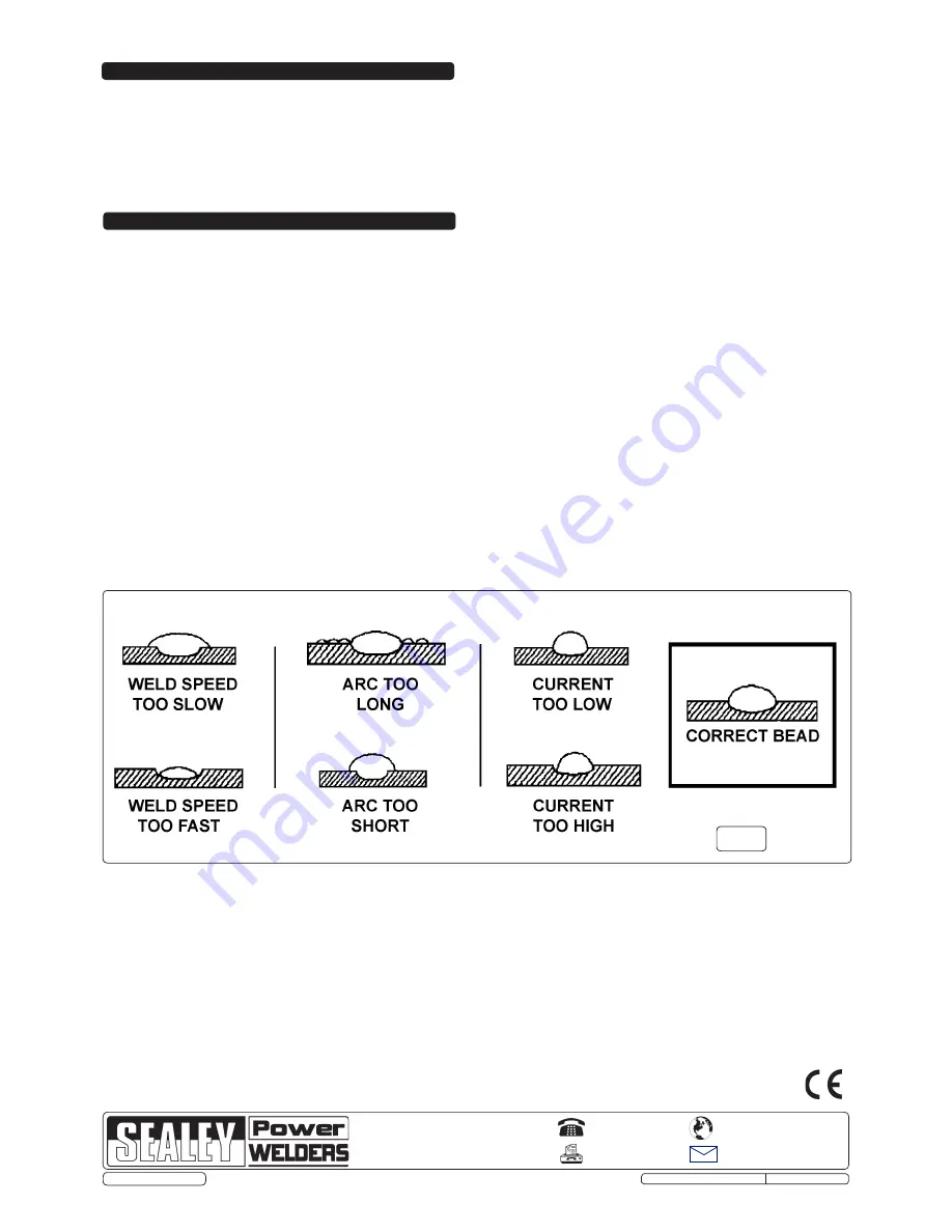
a) Refer to weld bead diagram (fig.7).
b) Check condition of electrode. It should be ground to the correct shape as seen in section 4 and should be symmetrically conical.
c) Check that correct gas flow is being used.
d) Check that correct ceramic nozzle is fitted to torch.
10.1.4.
Difficulty in striking an arc.
This is usually due to the electrode not being in good condition. Grind to correct shape or replace.
10.2.
MMA WELDING.
10.2.1.
Burning through thin metal.
On very thin sheet, e.g. car bodywork, the lowest amperage setting may be too fierce. In this case revert to TIG welding.
10.2.2.
Machine cuts out.
Refer to fault indicator information in section 10.1. above.
10.2.3.
Difficulty in striking an arc.
a) The electrode is damp. Heat it up before using.
b) Wrong type of rod.
NOTE:
It is our policy to continually improve products and as such we reserve the right to alter data, specifications and component parts without prior notice.
IMPORTANT:
No liability is accepted for incorrect use of this product.
WARRANTY:
Guarantee is 12 months from purchase date, proof of which will be required for any claim.
INFORMATION:
For a copy of our latest catalogue and promotions call us on 01284 757525 and leave your full name and address, including postcode.
01284 757500
01284 703534
Sole UK Distributor, Sealey Group,
Kempson Way, Suffolk Business Park
,
Bury St. Edmunds, Suffolk,
IP32 7AR
www.sealey.co.uk
Web
fig.7
Original Language Version
TIG160S, TIG180S, TIG200S Issue: 1 - 05/06/13
© Jack Sealey Limited