Sealey TIG160S Instructions Manual Download Page 4

  4.    PREPARING INVERTER FOR USE

  3. CONTROLS 

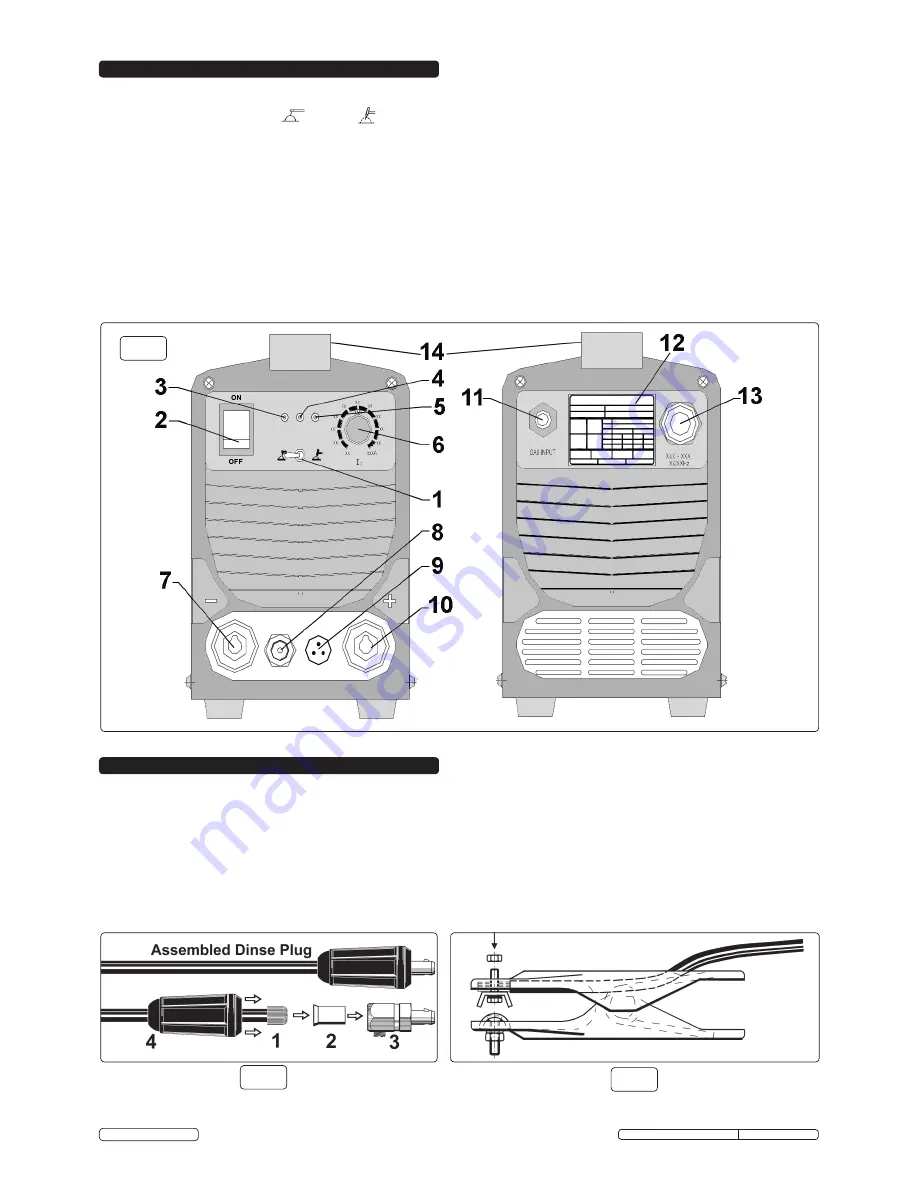
3.1.  FRONT AND REAR PANEL LAYOUT (fig.2).


1.


OPERATING SWITCH - MMA

           (left) / 

TIG

         (right) selection.


2.


MAIN ON/OFF SWITCH

.

 3.


GREEN LED 

- illuminates to indicate that power is on. 


4.


YELLOW LED - 

illuminates to indicate that the machine is locked: 

Thermal Relay.

 The temperature inside the welder is too high. The welder will 


reset its standard default settings automatically when cool (duty cycle, see section 2.2 for duty cycle percentages).


5.


RED LED - 

illuminates to indicate welder is working. 


6.


CURRENT SELECTOR DIAL.

 7.


DINSE SOCKET

 (negative 

-

). For the connection of a welding cable Dinse plug.


8.  GAS OUTPUT.


9.  TORCH CONTROL WIRE CONNECTION.


10. DINSE SOCKET

 (positive 

+

). For the connection of a welding cable Dinse plug. 


11. GAS INPUT.


12. RATINGS PLATE.


13. MAINS INPUT CABLE.   


14. HANDLE.

4.1.


CONNECTION TO THE MAINS.


Connection to at least a 32Amp fused supply is recommended. Seek the advice of a qualified electrician for    


connection to a suitable supply.

4.2.


WELDING CABLE CONNECTIONS.


The torch cable is supplied ready assembled but it may be necessary for you to assemble the work clamp cable.    


Attach the work clamp to one end of the cable as shown in fig.4. To connect the Dinse Plug as shown in fig.3 first thread the cable through the outer  


cover of the plug (see fig.3 - 4). Now remove 20mm of insulation sheath from the end of the cable and fold back the copper wire all around the outside of  


the sheath (1). Push the cable end into the copper sleeve (2) so that the folded back wire makes good contact with the inside of the sleeve. Push the    


copper sleeve into the brass plug body (3) and tighten the large grub screw until the cable is firmly held. Now slide the outer plug cover up the cable and  


press the brass body into it as shown in fig.3.

fig.3

fig.4

fig.2

Original Language Version

 TIG160S, TIG180S, TIG200S    Issue: 1 - 05/06/13

 © Jack Sealey Limited

Summary of Contents for TIG160S

Page 1: ...INSTRUCTIONS FOR TIG MMA INVERTER WELDERS 160Amp 180Amp 200Amp 230V TIG160S TIG180S TIG200S MODEL No s Original Language Version TIG160S TIG180S TIG200S Issue 1 05 06 13 Jack Sealey Limited ...

Page 2: ... a safe dry childproof area 1 1 ELECTRICAL SAFETY WARNING It is the user s responsibility to read understand and comply with the following You must check all electrical equipment and appliances to ensure they are safe before using You must inspect power supply leads plugs and all electrical connections for wear and damage You must ensure the risk of electric shock is minimised by the installation ...

Page 3: ...ed to assist with the explanations of symbols To determine the correct technical values of the machine please refer to the machine s individual data plate 1 Case protection grade IP21 Standard governing the required protection from water ingress and isolation of internal parts from persons and objects 2 Mains symbol AC single phase supply 3 Symbol S Indicates that welding operations may be carried...

Page 4: ...ction to at least a 32Amp fused supply is recommended Seek the advice of a qualified electrician for connection to a suitable supply 4 2 WELDING CABLE CONNECTIONS The torch cable is supplied ready assembled but it may be necessary for you to assemble the work clamp cable Attach the work clamp to one end of the cable as shown in fig 4 To connect the Dinse Plug as shown in fig 3 first thread the cab...

Page 5: ...GNETIC COMPATIBILITY THIS EQUIPMENT IS IN CONFORMITY WITH THE EUROPEAN STANDARD EN 50199 ELECTROMAGNETIC COMPATIBILITY OF ARC WELDING EQUIPMENT AND SIMILAR PROCESSES e g MMA AND TIG WELDING 5 1 PROTECTION AGAINST INTERFERENCE E M C The emission limits in this standard may not however provide full protection against interference to radio and television reception when the welding equipment is used c...

Page 6: ...s are to be performed and the welding parameters are unknown it is advisable to carry out several trial runs on test pieces in order to determine the right welding current and gas flow SWITCH ON the welder only when you are satisfied that the welder is correctly connected and the workpiece is fully prepared 7 1 SETTING THE CONTROLS 7 1 1 Set the required gas flow using the knob on the gas regulato...

Page 7: ... c Electrode does not match the collet and collet body fitted within the torch Obtain and fit the correct size of torch components for the electrode selected d Bad connection in welding cable and or work clamp has made poor connection with workpiece Check and clean all connections 10 1 3 Poor weld quality a Refer to weld bead diagram fig 7 b Check condition of electrode It should be ground to the ...

Reviews: