


Original language version
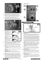
On the front panel of the welder is the rating plate, giving the following
data:
1 -
The BS/EU standard relating to the safety and construction of
arc welding and associated equipment.
2
- Inverter-transformer-rectifier symbols
3 -
Symbol indicates welding with a continuous flow of welding wire.
4 -
Symbol for Single-phase AC supply.
5 -
Rating of internal protection provided by casing.
6 -
Output.
U
0
: Maximum open-circuit voltage.
I
2
, U
2
: Current and corresponding voltage.
X: Welding ratio based on a 10 minute cycle. 20% indicates 2
minutes welding and 8 minutes rest, 100% would indicate
continuous welding.
7 -
Mains Supply. U
1
: Rated supply voltage and frequency.
I
1
max: Maximum current. I
1
eff: Maximum effective current.
8 -
A/V - A/V: Welding current adjustment range and corresponding voltages.
9 -
Serial Number. Specifically identifies each welder.
fig.12
fig.11
fig.10
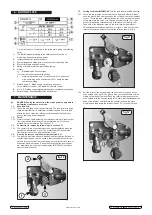
7.5. Turning feed roller
IMPORTANT:
Turn the feed roller to suit the wire size.
7.5.1. There are two grooves on the feed roller, 0.6mm and 0.8mm. Always
have the groove that is being used on the outside of the roller (nearest
to you). To turn the feed roller first loosen the knob on the wire tension
screw and move the screw into its down position (see fig.10-1), then
move the tensioning roller assembly to its up position (see fig.10-2).
Take hold of the triangular knob on the roller retainer and rotate it
90°anticlockwise to release it as shown in fig.10.3. Now pull the roller
retainer off the drive spindle to reveal the roller as shown in fig.11.
7.5.2. Pull the roller off the drive spindle, flip it over and put it back on the
drive spindle. (See fig 12) The groove size you require should now be
visible on the face of the roller. Push the roller retainer back onto the
drive spindle with the opening facing left. Ensure that the flanges at the
base of the retainer, seat fully into the circular recess in the main
moulding and then rotate the retainer through 90° to lock it in place.
DANGER! Unplug the welder from the mains power supply before
performing maintenance or service.
7.1. Wire feed unit:
7.1.1. Check the wire feed unit at regular intervals. The feed roller wire guide
plays an important part in obtaining consistent results. Poor wire feed
affects the weld. Clean the rollers weekly, especially the feed roller
groove, removing all dust deposits.
7.2. Torch:
7.2.1. Protect the torch cable assembly from mechanical wear. Clean the liner
from the machine forwards by using compressed air. If the liner is
blocked it must be replaced. See section 7.6.
7.3. Contact tip
(to remove tip follow steps in section 4.5)
7.3.1. The contact tip is a consumable item and must be replaced when the
bore becomes enlarged or oval. The contact tip MUST be kept free
from spatter to ensure an unimpeded flow of gas.
7.4. Gas cup
(to remove cup follow steps in section 4.5)
7.4.1. The gas cup must also be kept clean and free from spatter. Build-up of
spatter inside the gas cup can cause a short circuit at the contact tip
which will result in either the fuse blowing on the printed circuit card, or
expensive machine repairs. To keep the contact tip free from spatter,
we recommend the use of anti-spatter spray (MIG/722307) available
from your Sealey dealer.
6. RATING PLATE
7. MAINTENANCE
© Jack Sealey Limited
SUPERMIG140 Issue No:2(L) 05/08/14