
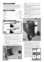


Original language version
5.1. Mig/Mag welding.
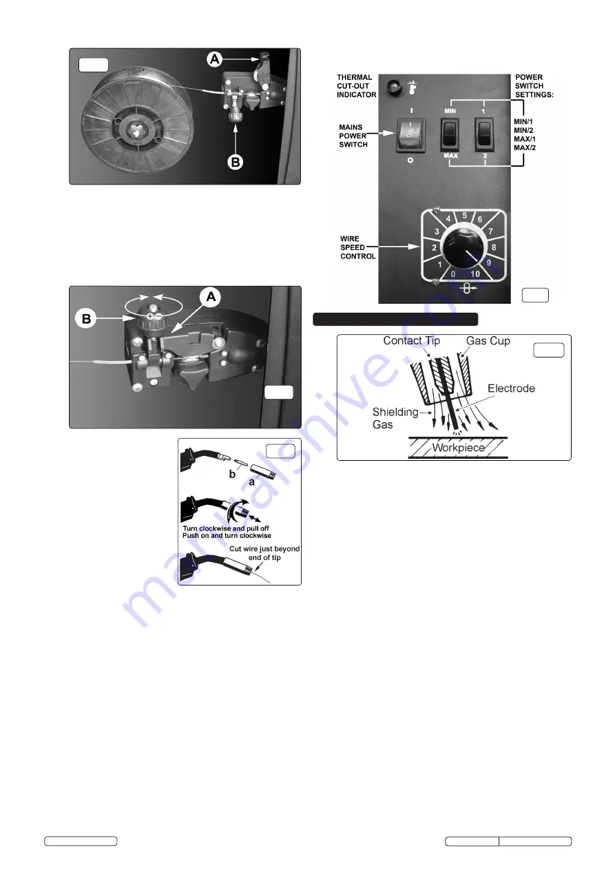
Welding wire is automatically fed through an insulated liner to the tip of
the torch. The torch consists of a switch, liner, gas hose, and control
cable. The switch activates the wire feed roller and the gas flow.
Releasing the switch stops wire feed and gas flow. The weld current is
transferred to the electrode (the wire) from the contact tip at the torch
end. The current to the electrode is set using the two switches on the
front of the control panel. Wire speed must be adjusted according to
current output using the rotary control below the power switches. The
higher the current the faster the wire speed. A gas cup fits over the
contact tip to direct gas flow towards the weld, (See fig.9) ensuring that
the arc welding process is shielded from oxidisation. The shielding gas
also assists heating of the weld. The torch is connected to the positive
side of a DC rectifier, and the negative clamp is attached to the
workpiece.
5.2. Preparation for welding:
IMPORTANT! BEFORE YOU COMMENCE,
MAKE SURE THE MACHINE IS SWITCHED OFF AT THE MAINS. IF
WELDING A VEHICLE, DISCONNECT THE BATTERY OR FIT AN
ELECTRONIC CIRCUIT PROTECTOR (AVAILABLE FROM YOUR
LOCAL SEALEY DEALER). ENSURE THAT YOU READ,
UNDERSTAND AND APPLY THE SAFETY INSTRUCTIONS IN
SECTION 1.
5.2.1. To ensure a complete circuit, the negative lead must be securely
attached to the workpiece close to the weld area. Best connection is
obtained by grinding the point of contact on the workpiece before
connecting the clamp.
5.2.2. The weld area must be free of paint, rust, grease, etc.
5.3. Gas types and their use.
Welding mild steel with CO² gas is appropriate for most welding tasks
where spatter and high build-up of weld do not pose a problem. To
achieve a spatter free and flat weld however, requires an Argon/CO²
mixture.
5.3.1. To weld aluminium use:
Argon Gas
0.8mm Contact Tip
0.8mm
Aluminium Wire (MIG/2/KAL08).
5.4. Thermal Protection.
Should the welder become overheated due to prolonged use beyond
the stated duty cycle, the thermal protection will cause the welder to cut
out and the amber light on the front panel will illuminate. Wait for fifteen
minutes for the welder to cool down at which time it will reconnect
automatically.
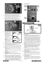
fig.9
fig.8
4.7 Control panel functions.
4.7.1 Refer to fig.8 below.
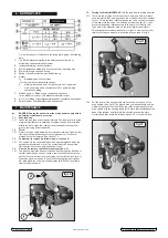
4.4.3. Referring to fig.5 turn the knob on the wire tension screw (B) anti-clock
wise and unlatch it from the pressure roller moulding. Swing the
pressure roller moulding (A) up and away from the drive roller.
4.4.4. Straighten 40-50mm of spool wire (do not allow wire to uncoil), and
gently push wire through the plastic guide and through the 6 or 8mm
feed roller groove and into the torch liner. Refer to section 7.5
on how to reverse the roller for either 6 or 8mm wire.
4.4.5. Referring to fig.6, move the pressure roller moulding (A) back
round onto the grooved drive wheel and swing the wire tension
screw (B) up to lock it in place. See 4.6 regarding wire tension.
fig.5
4.5. Feeding the wire through
to the torch.
(See fig.7)
Remove gas cup (a) and
contact tip (b) from end of
torch as follows:
a)
Take torch in left hand with
the torch tip facing to the right.
b)
Grasp gas cup firmly in
your right hand.
c)
Turn gas cup clockwise
only and pull cup out to the
right.
WARNING!
do not turn gas
cup anti-clockwise, as this will
damage internal spring.
d)
Unscrew the copper
contact tip (right hand thread)
to remove.
4.5.1. Check welder is switched off “0” and that the earth clamp is away
from the torch tip. Connect the welder to the mains power supply
and set the voltage switches to MIN/1. See fig.8.
4.5.2. Set the wire speed knob to position 5 or 6. Turn on the mains
power switch on the front panel. Keeping the torch cable as straight
as possible press the torch switch. The wire will feed through to
the torch.
4.5.3. When wire has fed through, switch welder off, unplug from mains.
a) Take torch in left hand, slide contact tip over the wire and screw
it back into place.
b) Grasp gas cup in right hand, push onto torch head and turn clockwise
only.
WARNING!
do not turn gas cup anti-clockwise, as this will damage
internal spring.
c) Cut wire so that it is just protruding from the cup.
4.6. Setting wire tension.
IMPORTANT:
You must set the correct tension, too little or too
much tension will cause problematic wire feed and result in a poor
weld.
4.6.1. For mild steel 0.6mm wire the wire tension screw must be fully
tightened and undone approximately two complete turns (fig.6).
4.6.2. Correct tension between the rollers is checked by slowing down the
wire between the fingers. If the pressure roller skids the tension is
correct. Try to use the lowest tension possible as too high a tension
will deform the wire and may result in blowing a fuse on the printed
circuit board. When you have completed welding disconnect the
unit from the mains supply and store it in a safe, dry place.
Note
: Damaged torches and cables are not covered under warranty.
fig.6
fig.7
5. WELDING PRINCIPLES
© Jack Sealey Limited
SUPERMIG140 Issue No:2(L) 05/08/14