


p
p
WARNING! Before following any of the steps below ensure the bandsaw is switched off,
isolated from the mains power supply and at a complete standstill. Failure to comply with this instruction can cause serious injury.
5.10.
Changing blades
NOTE: In order to assist with the removal of the blade it is recommended that the two blade guide assemblies are first removed.
The coolant supply piping can be removed without being disconnected. Carefully place the assembly to one side, in a position where
there is no possibility of it falling and substaining any damage.
5.10.1. Remove the yellow blade guard and the brush.
5.10.2. Raise the saw arm to a vertical position and lock in place by turning off the hydraulic cylinder at valve (fig.3.A).
5.10.3. Open the blade cover (located on the back of the arm) by removing the two screws.
5.10.4. Loosen blade tension by turning blade tension knob (fig.4.A) anti-clockwise and carefully remove the blade.
Caution: Blade teeth are sharp, handle with care.
5.10.5. Place new blade between guide bearings (if not removed) and then around both wheels, ensuring blade edge rests near each wheel flange.
NOTE:
The teeth must be pointing in the correct direction (indicated on the label found on the saw arm).
5.10.6. Tension blade (see para. 5.3.4 & 5).
Do not over tension
.
5.10.7. Close the blade cover and secure with the screws.
5.10.8. Replace blade guides, if removed, and re-attach the blade guard and blade brush.
5.10.9. Adjust the blade guides as described in para. 5.8.
5.11.
Adjusting bow weight
NOTE:
Incorrect bow weight can cause crooked cuts, tooth stripping, stalling and the blade to ride off the wheels. The hydraulic feed
rate unit will not compensate for improper bow weight and if adjustment is necessary proceed as follows:
5.11.1. Turn the hydraulic cylinder valve on and place the saw arm in the horizontal position.
5.11.2. Turn the feed rate valve (fig.3.B) on the hydraulic cylinder fully anti-clockwise.
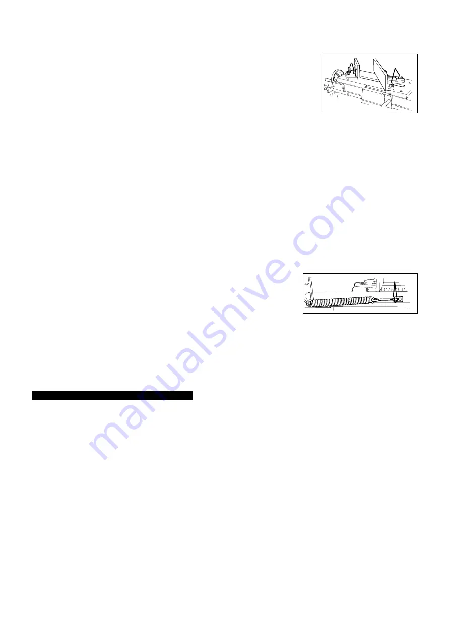
5.11.3. Place the hook of a spring balance around the blade tension handle spindle and pull the saw
arm up. The spring balance should indicate 5-6 kg.
5.11.4. If necessary, adjust the tension to 5-6 kg by turning the nuts (fig.8.A) on the spring adjusting
rod. When adjustment is complete tighten both nuts to lock rod in position.
5.12.
To adjust blade tracking
NOTE:
Blade tracking is factory set and should not require adjustment. However, if it does become necessary, proceed as follows:
5.12.1. Run saw for a short time and then switch off.
5.12.2. Raise saw arm, open blade cover and check blade-to-wheel relationship (tracking). Rear edge of blade should be very close to, but
not hard against, the wheel flanges.
5.12.3. If inspection indicates that adjustment is required loosen the two locking screws (fig.4.B) and adjust set screw (fig.4.C) - turn clockwise
to track blade closer to flange and anticlockwise to track away. Retighten screws.
5.12.4. Having made a small adjustment
close the blade cover
and run the saw for a short time.
5.12.5. Switch saw off, open blade cover and check tracking. Repeat adjustment procedure if necessary.
6. MAINTENANCE
p
p
p
WARNING! Before carrying out any maintenance ensure that the bandsaw is switched off, isolated from the mains supply
and that the blade is at a complete standstill. Failure to comply with this instruction can cause serious injury.
6.1.
Lubrication
6.1.1. Ball bearings on the blade guide assemblies and blade wheels are permanently sealed requiring no lubrication.
6.1.2. Keep all surfaces clean and free of rust, swarf and coolant build-up.
6.1.3. Lightly lubricate vice screw with grease.
6.2.
Changing gearbox oil
6.2.1. Change gearbox oil after the first 90 days of operation and thereafter every six months.
6.2.2. Place the saw arm in the horizontal position.
6.2.3. Remove screws from gearbox cover, to left of motor, and remove the cover plate and gasket.
6.2.4. Hold a container under the lower right corner of the gearbox, while slowly raising the saw arm.
6.2.5. When the oil flow stops, return the saw arm to a horizontal position and wipe out any remaining oil with a rag.
6.2.6. Fill the gearbox with approximately 300ml of 90 weight gear oil.
6.2.7. Replace the cover plate and gasket, and fasten securely with the screws.
6.3.
General maintenance
p
WARNING! Do not use compressed air to clean the bandsaw as metal filings may blow into the blade guide bearings and
other critical areas. There is also a danger of flying particles being released into the surrounding area.
6.3.1. Use a small paint brush or parts cleaning brush to remove metal particles. If inaccessible (and ferrous) use a magnetic pick-up tool.
6.3.2. Regularly wipe the saw down with a clean dry cloth and oil all unpainted surfaces with light machine oil.
6.3.3. Keep blade guides clean and free of metal filings.
6.3.4. Check the guide bearings frequently to make sure they are properly adjusted and turning freely.
6.4.
Blade cleaning brush
6.4.1. Replace the brush as soon as it becomes worn or damaged or blade life will be significantly shortened.
SM35CE - 0016 - (4) - 140301
5.8.2. Loosen the hex. cap screw (fig.6.B) on the guide assembly and adjust the rear bearing to within 0.08 - 0.12 mm of the blade.
5.8.3. Loosen lock nut (fig.6.C) and turn the front bearing eccentric (fig.6.D) so that bearing is snug with the blade. The blade should still
move up and down freely if grasped. Repeat the procedure for the other guide assembly.
5.9.
Adjusting the vice
NOTE: Do not adjust the vice or load/unload any material while the saw is running.
The
vice can be adjusted to hold the workpiece at angles between 0
°
and 45
°
.
5.9.1. Slacken the bolts (fig.7.A) clamping the fixed vice.
5.9.2. Position the vice at the desired angle and tighten bolts.
5.9.3. Loosen the bolts (fig.7.B) on the moveable vice and turn it to match the angle of the fixed vice. Tighten
bolts when vice faces are parallel.
fig. 7
A
B
fig. 8
A


