


2. introDUCtion
Sm2503a metal working mini lathe 250mm
B
ench mounting minature lathe small enough to fit into the corner of a workshop and light enough to be truly portable. Construction is
predominately cast iron and steel. fitted with 150W high torque motor. the capacities are: 150mm swing over bed and 250mm between
centres. features variable speed control, manual or powered lead screw feed, overload protection and the availability of an extensive range
of accessories. the lathe comes with 80mm diameter 3 jaw self centring chuck, tailstock centre and service tools. option to upgrade with a
mill/drill head.
Sm2503B Drill head (only to be used in conjunction with Sm2503a) never plug into mains supply
t
ransforms Model no:SM2503A Metal Working Mini Lathe into a Lathe/Mill Drill combination. Easily retro fitted, this drill head offers the
flexibility to handle most materials. This space efficient versatile lathe mill/drill machine features a 150W motor.
3. SpeCifiCation
model no: .............................................................. Sm2503a
swing over bed: ......................................................... 150mm
distance between centres: ......................................... 250mm
spindle hole taper: ..........................................................mt2
cross slide travel: ........................................................ 61mm
tailstock taper: ................................................................mt1
spindle speed (variable): ..................................100-2000rpm
range of metric threads: ................... 5 pitches (0.5-1.25mm)
motor power: ....................................................... 150W-230V
Weight: ........................................................................... 23kg
Drill head sold separately only as an accessory for Sm2503a
model no: .............................................................. Sm3503B
max/min drilling/milling capacity: .................................. 10mm
drilling/milling spindle travel: ........................................ 30mm
spindle taper: ..................................................................mt2
drilling/milling spindle speed: ............................100-1500rpm
t-slot: ............................................................................. 8mm
distance from spindle to table: ................................... 180mm
distance from spindle centre to column: .................... 100mm
motor power: ................................................. 150W-230V dc
Weight: ........................................................................... 22kg
4. aSSemBly lathe
warning! at least two people are required to move the lathe. observe good lifting practice.
4.1.
unpack and check that everything is present and undamaged.
4.2.
the machine has been coated with heavy grease to protect it in shipping. remove the coating with commercial degreaser, kerosene
or similar solvent before operating. Avoid getting the solvent on rubber parts. After degreasing coat the machined surfaces with a
medium consistency machine oil.
4.3.
mounting the machine.
4.3.1.
locate the machine on a level and strong work surface.
Do not
locate in direct sunlight or where heavy dust or moisture is
present.
4.3.2.
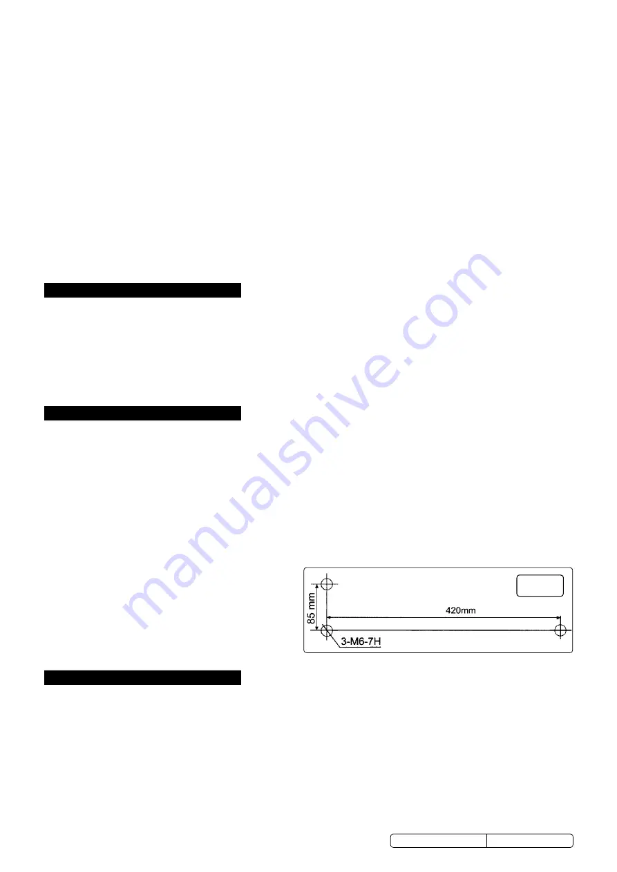
drill the location holes in accordance with the dimensions shown in fig.1 and bolt the machine to the bench securely using three m6
bolts (not provided.)
4.4.
fit the handles to the handwheels.
fig.1
sm2503A, sm2503B issue:1 - 21/09/15
Original Language Version
© Jack sealey limited
warning!
Keep chuck guard and holding fixings in place, tight and in good working order. the safety micro switch ensures that the lathe
and drill head will not operate when the chuck guard is raised. check regularly for damaged parts.
A chuck guard that is damaged or missing must be repaired or replaced before the lathe and drill head are next used.
warning!
Do not
over-ride the chuck guard safety micro switch.
remove adjusting keys and wrenches from the lathe and drill head and its vicinity before turning it on.
warning!
Wear approved safety eye protection and, if oil mist is generated, respiratory protection.
remove ill fitting clothing. remove ties, watches, rings and other loose jewellery and contain long hair.
Keep hands and body clear of the workpiece when operating the lathe and drill head.
maintain correct balance and footing. ensure that the floor is not slippery and wear non-slip shoes.
Keep children and unauthorised persons away from the work area.
warning!
Do not
switch on the lathe or drill head whilst the cutting tool is in contact with the workpiece. Bring the cutting tool gradually
to the workpiece.
Avoid unintentional starting of the lathe and drill head.
Do not
use the lathe or drill head for a task it is not designed to perform.
Do not
allow untrained persons to operate the lathe or drill head.
Do not
get the lathe or drill head wet or use in damp or wet locations or areas where there is condensation.
warning! Do not
use the lathe or drill head where there are flammable liquids, solids or gases such as petrol, paint solvents, waste
wiping rags etc.
Do not
operate the lathe or drill head if any parts are missing or damaged as this may cause failure and/or personal injury.
Do not
lift or remove the chuck guard whilst the lathe is in use.
Do not
touch the workpiece close to the cut as it will be very hot. Allow to cool.
Do not
leave the lathe or drill head running unattended.
Do not
operate the lathe or drill head when you are tired or under the influence of alcohol, drugs or intoxicating medication.
When not in use switch off the lathe and isolate from the power supply.