


p
p
WARNING! Ensure that you have read, understood and apply Section 1 safety instructions.
4.1
STARTING THE COMPRESSOR
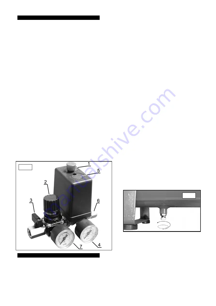
4.1.1 Check that the start button (fig 1.1) is in the OFF position (down), the regulator (fig 1.2) is closed (Zero 0 bar), and tap (fig 1.3)
is Closed (as shown).
4.1.2 Plug the compressor into the electrical mains supply and start the machine by moving the start button into the ON position (up).
4.1.3 The compressor will now operate and automatically build up the pressure in the tank to the maximum pressure set at the factory and
may be monitored by reading pressure gauge (fig 1.4). When the maximum tank pressure is reached, the pressure switch (fig 1.5)
will automatically switch the motor off. When pressure falls below the minimum threshold (approx. 2 bar (29psi) less than the
maximum pressure), the pressure switch (fig 1.5) will automatically cut in and start the motor again, thus building the pressure back to
maximum.
NOTE:
a) If the motor does not cut in and out, but runs continuously when using an air appliance, the capacity of the compressor may be too
small for the equipment or tool.
b) The gauge (fig 1.4) indicates the pressure inside the main tank, NOT the pressure supplied to the air equipment. Should the
pressure in the main tank exceed the pre-set switch (fig 1.5) maximum, a safety release valve (fig 1.6) will activate.
WARNING! for this reason DO NOT tamper with or adjust the switch or valve unit.
4.2
STOPPING THE COMPRESSOR
To stop the compressor, move the start button to the OFF position (down). This switch will stop the motor and open a breather
valve to release pressure from the motor head, which makes restart easier and prevents the motor from being damaged.
CAUTION! DO NOT turn off from the electrical mains power switch (other than in an emergency), as the head pressure relief will not
occur.
4.3
CONNECTING AIR POWERED EQUIPMENT
4.3.1 After fitting the desired coupling to tap (fig 1.3) connect other end of the hose to the air equipment.
4.3.2 Turn the regulator valve (fig 1.2) to the required output pressure. The pressure applied to the tool is shown on the output pressure
gauge (fig 1.7).
4.3.3 Turn on tap (fig 1.3).
NOTE:
To determine the correct working pressure and air flow requirements for any piece of equipment check the corresponding
manual. Be aware that the air flow figure stated on tools and accessories refers to Free Air Delivery and not the piston displacement
of the compressor.
4.3.4 To disconnect equipment, turn the regulator valve (fig 1.2) anti-clockwise to Zero (0) bar. Pull the air equipments trigger to release
pressure and then disconnect air hose from compressor. Relieve any pressure remaining in the compressor by manually operating the
pressure relief button situated below the compressors air outlet. Push the button inwards to relieve the pressure.
4.4
WHEN WORK IS COMPLETE
Ensure the the compressor is switched off and the pressure is released before draining the tank.
At the end of each working day, drain any moisture from the main tank. Place a container under the drain valve on the underside of
the tank (fig 2) and carefully unscrew the drain valve to allow any moisture to escape. When moisture ceases to come out screw the
valve back up, again ensuring that it re-seals. DO NOT allow moisture to accumulate in the tank as this will corrode the inside and
affect the tanks pressure rating.
WARNING!
Wear safety goggles when performing this task.
NOTE:
As the residue is oil-free it may be disposed of through the normal sewage system.
In order to keep the compressor in good working condition, periodic maintenance is essential.
p
p
WARNING! service and maintenance must be performed by an authorised agent. DO NOT tamper with, or attempt to adjust, pressure switch or
safety valve. Before moving, or carrying out any maintenance on the compressor, ensure that it is unplugged from the mains power
supply and that the air tank pressure has been vented.
5.1
GENERAL WORKSHOP MAINTENANCE
At the end of each working day, drain any moisture from the main tank as described above in section 4.4.
WARNING!
Wear safety goggles when performing this task.
NOTE:
As the residue is oil-free it may be disposed of through the normal sewage system.
5. MAINTENANCE
fig 2
4. OPERATION
SA951015, SA952515 & SA955015 - 1 - 310105
fig 1


