4.4.
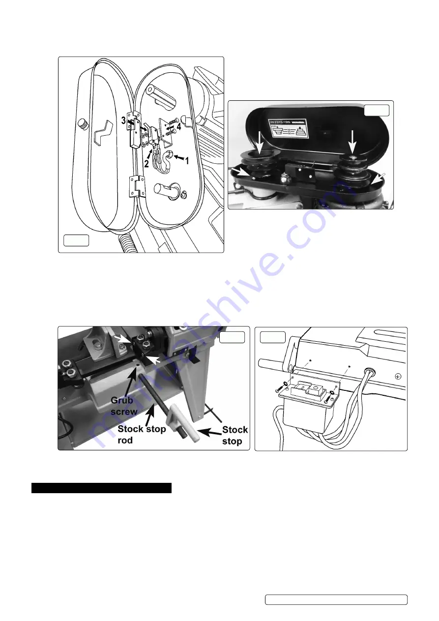
Fit the microswitch Refer to the numbers in fig.10
4.4.1.
Slide the cover off the microswitch and fit the connectors, they can go either way round.
4.4.2.
slide the cover back over the microswitch and bolt it to the bracket.
4.5.
Fit the motor and driven pulleys and drive belt Refer to fig.11
4.5.1.
Fit the motor pulley making sure the key is in place, tighten the grub screw when the pulley is flush with the end of shaft.
4.5.2.
Fit the driven pulley making sure the grub screw lines up with the flat on the shaft.
4.5.3.
make sure both pulleys are the same distance from the belt guard and that the top faces of both pulleys are level, see white arrows
in fig.11. Tighten the grub screw.
4.5.4.
Fit the drive belt and adjust motor position (using screw and locknut) to tension the belt, see fig.8.
4.6.
fit stock stop
4.6.1.
Fit the stock stop rod (21) into the base and secure with the grub screw. Fit the stock stop (19) and secure with screw (20), see
fig.12.
4.7.
fit the switch box
it is stROngly advised tHat all electRical wORK be undeRtaKen by a fully Qualified electRician.
4.7.1.
Fit the switch box using the screws provided, see fig.13.
5. set up
5.1.
adjust the abutment screw
(53) so that with the body frame down the blade cutting edge is below the surface of the base, but the
body frame is clear of the base. Tighten the lock nut (122), see fig.14.
5.2.
adjust switch cut off tip
(76) to ensure that ‘Off’ switch is actuated when or just before body frame contacts the abutment screw
(53). Tighten the screw which secures the switch cut off, see fig.15.
5.3.
adjust the blade speed
5.3.1.
Adjust blade speed to suit the metal to be cut. The recommended pulley selections are shown in fig.16.
5.3.2.
disconnect the saw from the power supply and open the pulley cover.
5.3.3.
Loosen the tension screw (98) on the motor plate, see fig.8, to slacken the belt. Move the belt to the required pulley grooves
(see fig.16). Tension the belt by tightening screw (98). Close the cover.
5.4.
blade selection
5.4.1.
The chart in fig.16 shows the recommended set up for various metals and cut lengths. Blades are available from your Sealey
stockist in four tooth pitches: 6, 10, 14 and 24tpi (see parts list).
fig.11
fig.10
fig.13
fig.12
Original Language Version
© Jack sealey limited
s
M5.V3 Issue:7(H, F)13/02/18


