


5. OperatiOn
WarninG!
Before operating the machine ensure that you read, understand and apply section 1 safety instructions and that you
have familiarised yourself with the controls. ensure that the machine is disconnected from the power supply before moving or
changing accessories.
5.1.
set-up
(air supply connected in section 4)
5.1.1.
check that the earth cable is correctly clamped to the work piece or work bench.
5.1.2.
switch on the mains power supply. switch on the machine by operating the i/o switch on the rear panel (fig.1.2).
5.1.3.
set the current regulation control (fig.1.5) to the required value.
5.1.4.
Press the torch button and release to commence the flow of cooling air (post-air).
5.1.5.
Allow the air flow to continue to remove any condensation from the torch. the air flow will automatically stop after approx. 5secs.
note: longer than standard nozzles and electrodes are available to improve accessibility in awkward cutting positions.
5.2.
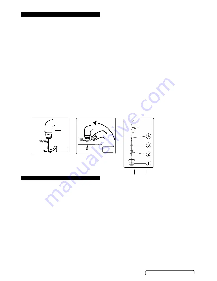
cutting from the edge
5.2.1.
Bring the torch nozzle toward the edge of the work piece and hold it at 3mm above the cutting line.
5.2.2.
Press and hold down the torch button. After about 1/5 of a second of pre-air, the pilot arc will be generated. if the distance between the
torch nozzle and the work piece is correct, the arc will immediately jump to the work piece and the cutting process will begin.
5.2.3. move the torch slowly and smoothly forward, on the surface of the work piece, along the cutting line.
5.2.4. Adjust the cutting speed according to the thickness of the material and the selected current.
5.2.5.
check the underside of the cut. the arc should make a 5 - 10° angle with the vertical in the opposite direction to the cutting direction
(fig.4).
6.3.
cutting from the centre
6.3.1.
Place the torch nozzle at an angle to the surface at the start-of-cut position (fig.5).
5.3.2.
initiate the pilot arc, then slowly and smoothly bring the torch head to the upright position.
the arc will pierce the work piece and cutting can start.
6.4.
arc off
6.4.1.
release the torch button to switch off the arc. the post-air will continue to flow, cooling the nozzle.
6.4.2.
other reasons for the arc ceasing are:
a) the distance between the torch nozzle and work piece is too great.
b) You have completed a cut and have continued beyond the edge of a work piece.
c) the waste falls away from the work piece thus increasing the gap.
6. maintenance
▲
DanGer!
Ensure that the machine is disconnected from the power supply before performing service or maintenance on any part of the
unit, cables or torch.
6.1.
the inverter
8
DO nOt
open the unit. service and maintenance of the machine must only be undertaken by an authorised service agent.
6.1.1.
Keep the machine clean by wiping with a soft cloth. do not use abrasives.
6.1.2.
Periodically check to ensure that the carrying handle is in good order and condition. if not replace it immediately.
6.1.3.
ensure that the front and rear air vents are not blocked.
6.2.
cables and leads
6.2.1.
check to ensure cables and leads are in good condition. if damaged, contact your authorised service agent.
6.2.2.
Keep cables and leads clean. do not use solvents.
6.3.
torch
check torch regularly. maintenance will depend on frequency and type of usage and is essential for correct and safe use of the torch.
WarninG!
ensure that the torch is cool before attempting any maintenance. Always re-assemble the torch in the correct order as shown in
(fig.6). never use tools to tighten nozzle components, hand tighten only.
6.3.1.
manually dismantle the torch nozzle head.
6.4.
cap
(fig.6.1)
clean cap and check to ensure it is not damaged (including distortion, burns, cracks). if in any doubt, replace.
6.5.
electrode
(fig.6.2)
check the build-up on the emitting surface of the electrode. When the build-up is approximately 2mm replace the electrode.
nOte:
We recommend that the electrode and nozzle are changed at the same time.
6.5.1.
air distribution ring
(fig.6.3)
check that the ring is not burned or cracked and that the airflow holes are not obstructed. if damaged replace.
6.5.2.
nozzle
(fig.6.4)
if the surface is oxidised, clean with extra fine abrasive paper. check wear of the plasma arc hole and the inner and outer surfaces. if
hole has widened, or nozzle is damaged in any way, replace it. the nozzle “V” crater should be 1.5mm in depth.
fig.4
fig.5
PP40e | issue2 22/12/16
Original Language Version
© Jack sealey limited
fig.6


