3. 4. FIT A REEL OF WIRE. Ensure the welder is unplugged from the mains power.
Machine is supplied with a mini spool of wire, but will accept up to 15kg spools without modification.
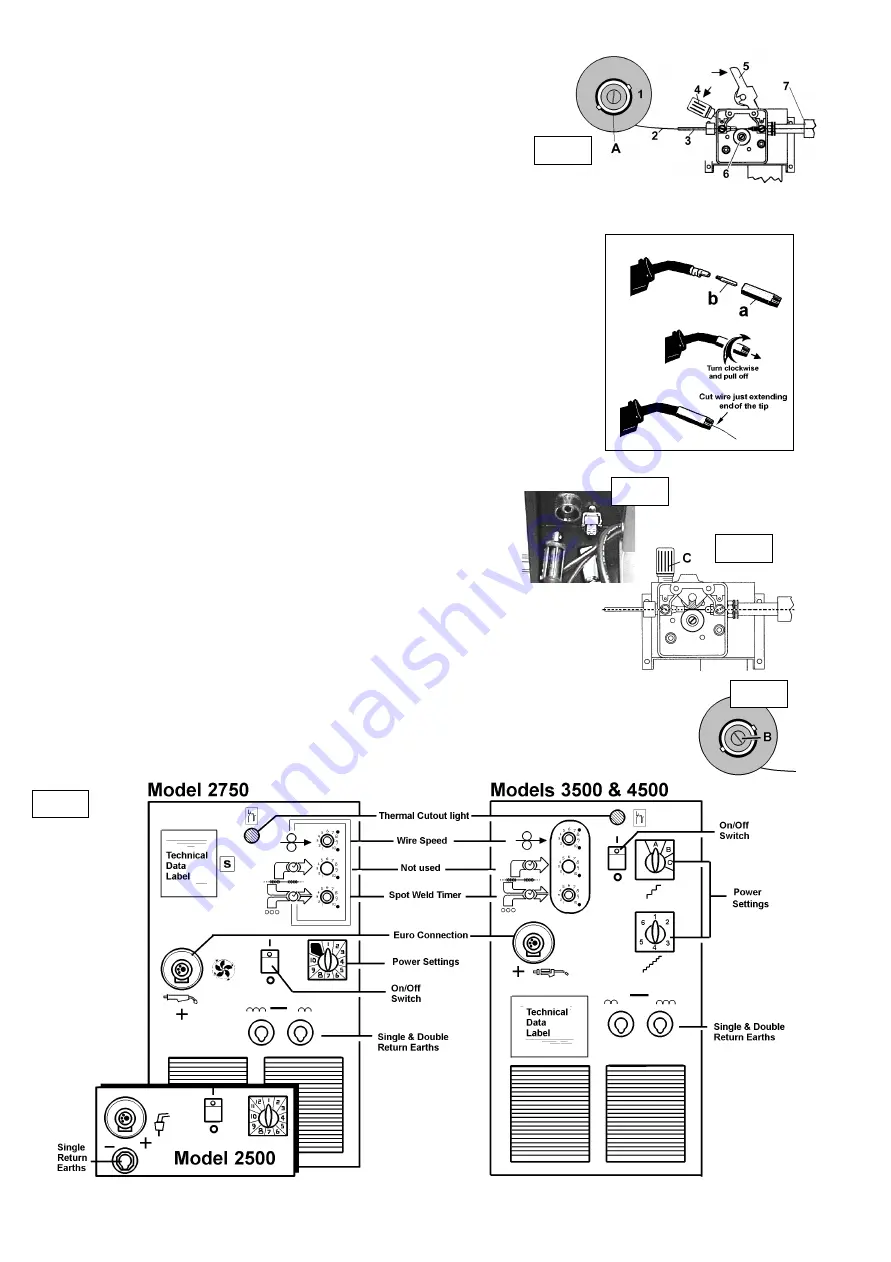
3.4.1. Open the side of the unit, remove the spacer from the holder (fig 5. A) and push the reel of
wire (fig 5.1) over the holder end springs and onto the holder ensuring the spool rotates
anti-clockwise with the wire drawing off the reel from the bottom (2). Large spools of wire have
a guide hole which must be pushed onto the plastic pin located at back of reel holder. When
large reel has been located on this pin, push the spacer (A) back onto holder to keep reel
pushed onto the pin. Pin will stop large reels from free wheeling around the holder.
3.4.2. Undo wire lock screw and lower to the left (4) and lift wire feed tension arm up to the right (5).
3.4.3. Straighten about 40-50mm of spool wire (2) (
do not allow wire to uncoil
). Round end of wire off
ensuring any burrs or sharp points are removed, and gently push wire through plastic guide (3) and through the 6mm
or 8mm roller groove (6) (refer to Maintenance for roller grove information) and through to torch (7). Note: Burrs or sharp
points at wire tip may damage the liner.
3.4.4. Carefully return the tension arm (5) and secure wire with the wire lock screw (4).
3.5.
FEED WIRE THROUGH TO THE TORCH.
3.5.1.
Models POWERMIG 4500 & 3500
Twist off gas cup then unscrew copper contact tip (
right hand thread
) to
remove.The reel is fitted to a portable feed unit inside the welder. Connect the two power supply leads from
the portable unit to sockets at the left side of the feed unit compartment (fig A). Then follow instruction points
3.5.3. to 3.5.5. Replace contact tip and gas cup. Cut wire so that it is protruding 1/4 from the cup.
3.5.2.
Model POWERMIG 2500, 2750
Remove gas cup (fig 6.a) and contact tip (b) from end of torch as follows:
a) Take torch in left hand with the torch tip facing to the right.
b) Grasp gas cup firmly in your right hand.( Cup is a friction fit.)
c) Turn gas cup
clockwise only (fig 6)
and pull cup out to the right.
p
WARNING!
do not turn gas cup anti-clockwise, as this will damage the internal spring.
d) Unscrew the copper contact tip (
right hand thread
) to remove.
3.5.3.
Models 2500 & 2750.
Check welder is switched off 0, and that the earth clamp is isolated and away from the torch tip. Connect the
welder to the mains power supply and set the voltage switch to 1.
Models 3500 & 4500
have a portable feed unit inside the welder. Connect the two power supply leads from
the feeder to plugs at the left of the unit (fig A). Connect to the mains power supply and set the voltage switch to 1.
3.5.4. Set the wire speed knob to position 5 or 6, (the higher the number the faster the speed). Keep the
torch cable as straight as possible and press the torch switch to feed wire through the torch.
3.5.5. When wire has fed through, switch welder off, unplug from mains.
3.5.6. Take torch in left hand and screw contact tip back into place as follow:
3.5.7. Grasp gas cup in right hand, push onto torch head and turn
clockwise only
.
p
WARNING!
do not turn gas cup anti-clockwise, as this will damage the internal spring.
3.6. SETTING WIRE TENSION.
IMPORTANT: You must set the correct tension, too little or too much tension will cause problematic wire feed
and result in poor welding.
3.6.1. Tension between rollers is checked by slowing down the wire between your fingers. If top feed roller skids the
tension is correct. Use as low a tension as possible, too high a tension will deform wire and result in a blown
fuse on the printed circuit board. Adjust tension by turning knob (fig 7.C).
fig 5
fig 7
Front Panel
Description
3.7.
CLUTCH ADJUSTMENT
It is essential that the clutch is adjusted correctly. Once the wire is fed through the torch, switch on the machine and set the wire
speed and voltage switch to maximum. Depress the torch switch and release quickly. If spool overruns it indicates that the clutch
is too loose. Tighten the clutch (located in the centre of the wire spool holder (fig 8.B), and test the machine as above until the
wire stops over running.
p
p
p
WARNING! DO NOT over tighten the clutch as this will cause wire feed problems.
fig 8
fig 9
fig A
fig 5
POWERMIG2500, 2750, 3500, 4500. - (0051) - (1) - 270100
fig 6


