fig 6
fig 7
fig 8
p
p
WARNING! Ensure the drill is unplugged from the mains power supply before commencing.
4.1
INSTALL DRILL BIT
4.1.1
Insert drill bit into chuck jaws to 1" (25mm) deep (avoid inserting small bits too far) and centre bit in chuck before tightening with the
supplied chuck key.
4.2
ADJUSTING THE TABLE
4.2.1
To adjust table up or down, loosen the column clamp bolt (fig 2.4) then turn the adjusting handle (fig 2.2).
4.2.2
To turn the table around the column, loosen the rack collar slightly, then loosen the column clamp bolt, turn the table to the desired
position then secure the bolt and the rack collar.
4.3
ADJUSTING THE SPEED
4.3.1
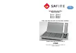
To adjust the speed of the drill, simply turn the speed control dial (fig 8) located on the opposite side of the drill to the feed handle
until the desired speed is shown on the digital display.
p
p
WARNING! Do not adjust the drilling speed while the drill is not running or when it is slowing down.
4.3.2
Choose the speed for drilling operation carefully before you begin to drill the workpiece (see drill speed chart - Section 5).
4.3.3
To reset the digital display during operation, press the reset button located below the LCD panel (fig 7.5).
4.4
POSITIONING THE WORKPIECE
4.4.1
To prevent table damage, rest the workpiece on a piece of wood.
The wood should rest on the table so that one end of it is against the left side of the column, to prevent it spinning when the drill bit
breaks through the workpiece.
4.4.2
For small workpieces that cannot be clamped to the table, use a drill vice (not included). Vice must be clamped or bolted to table.
4.5
SETTING THE DRILL DEPTH
4.5.1
Use the scale located on the collar of the feed handle.
4.5.2
Loosen the depth scale locking screw (fig 7.4) and set the scale to the depth desired. Tighten locking screw.
4.5.3
When ready to drill, simply pull the feed handle. The drill will stop at the set depth.
4. OPERATING INSTRUCTIONS
PDME160B-PDME200F - 1 - 151204