


4. WELDING PRINCIPLES
IMPORTANT:
These instructions are not intended to teach you how to weld. If you have no experience, we recommend that you seek
training from an expert source. MIG welding is relatively easy, but does require a steady hand and supervised practice on scrap metal, as it
is only with continued practice that you will achieve the desired results.
4.1. MIG/MAG welding:
Welding wire is automatically fed through an insulated liner to the tip of the torch. The torch consists of a switch, liner, and control cable.
The switch activates the wire feed roller. Releasing the switch stops wire feed. The weld current is transferred to the electrode (the wire)
from the contact tip at the torch end. The current to the electrode is set using the rocker switch on the front of the control panel. Wire
speed must be adjusted according to current output using the rotary control positioned to the left of the control panel. The higher the
current the faster the wire speed. The torch is connected to the positive side of a DC rectifier, and the negative clamp is attached to the
workpiece.
4.2. Preparation for welding: IMPORTANT!
BEFORE YOU COMMENCE, MAKE SURE THE MACHINE IS SWITCHED OFF AT THE MAINS.
IF WELDING A CAR, DISCONNECT THE BATTERY OR FIT AN ELECTRONIC CIRCUIT PROTECTOR. ENSURE THAT YOU READ,
UNDERSTAND AND APPLY THE SAFETY INSTRUCTIONS IN SECTION 1.
4.2.1. To ensure a complete circuit, the negative lead must be securely attached to
the workpiece close to the weld area..Best connection is obtained by grinding the
point of contact on the workpiece before connecting the clamp.
4.2.2. The weld area must be free of paint, rust, grease, etc.
4.3. Thermal Protection:
Should the welder become overheated owing to prolonged use beyond the
stated duty cycle the thermal protection will cause the welder to cut out and
the amber light on the front panel will illuminate. Wait fifteen minutes for
the welder to cool down at which time it will reconnect automatically.
fig.7
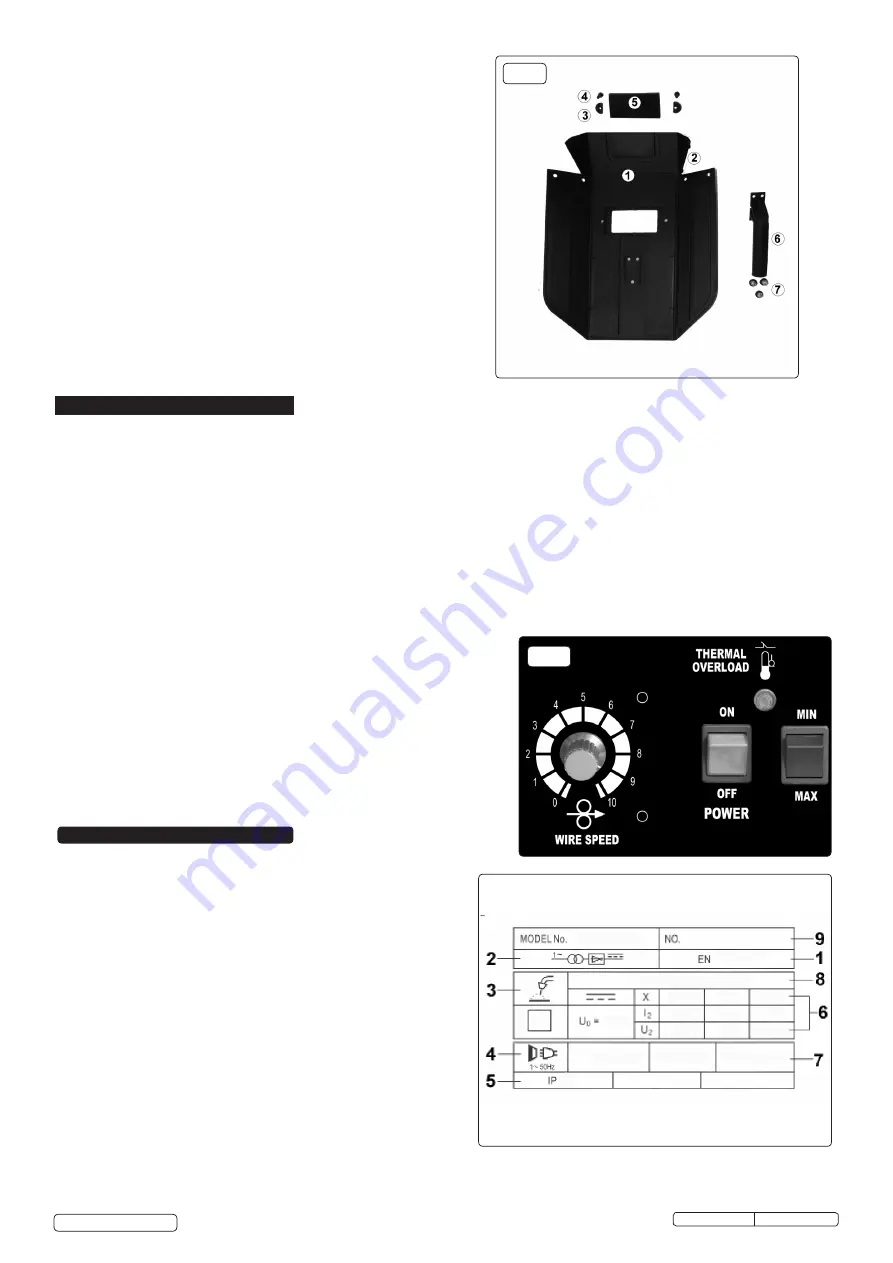
3..3. Assembling welding mask
3.3.1. Fold the mask body (fig.6.1) inwards until the pins (fig.6.2) line up
with the holes and press together.
3.3.2. Secure the lens retaining clips (fig.6.3) with the pins (fig.6.4)
3.3.3. Open the lens retaining clips, lower the lens assembly (clear glass
should be outermost) into the aperture and secure by turning the lens
retaining clips through 180°.
3.3.4. Secure the handle (fig.6.6) to the body by means of the three screws
(fig.6.7)
3.4.
Shoulder strap.
Fit the shoulder strap to the locations at the front and rear of the
welder casing.
fig.6
5. RATINGS PLATE
On the front panel of the welder is the ratings plate, giving the
following data:
1 -
The BS/EU standard relating to the safety and construction of
arc welding and associated equipment.
2
- Single phase transformer.
3 -
Symbol indicates welding with a continuous flow of welding wire.
4 -
Symbol for Single-phase AC supply.
5 -
Rating of internal protection provided by casing.
6 -
Output
U
0
Rated minimum and maximum no load voltage.
I
2
, U
2
Current and corresponding voltage.
X
Welding ratio based on a 10 minute cycle.
20% indicates 2 minutes welding and 8 minutes rest,
100%
would indicate continuous welding.
7 -
Mains Supply
U
1
Rated supply voltage and frequency.
I
1
max Maximum current.
I
1
eff Maximum effective current.
8 -
Welding current range.
9 -
Serial Number. Specifically identifies each welder.
MIGHTYMIG90.V2 Issue: 1 - 15/02/17
Original Language Version
© Jack Sealey Limited


