3. SPECIFICATION
Capacity ..........................................................................454kg
Min. height .....................................................................190mm
Max. height ....................................................................710mm
Width .............................................................................690mm
Length .................................................(platform only) 2200mm
Overall length ........................................... (inc. ramp) 2860mm
Air supply ................................................Min 100psi/Max 120si
OPE
RATION
Air supply ..................................................................... 1/4”BSP
4. ASSEMBLY
Unpack the lift and check contents with list below. Should there be any damaged or missing parts, contact your supplier immediately.
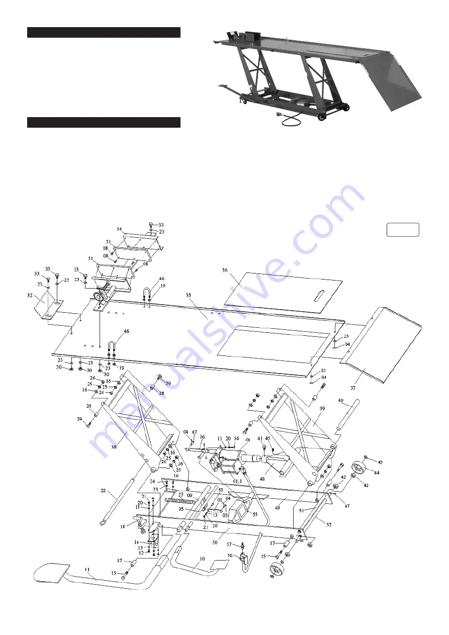
NOTE! All numbers refer to fig.1.
Contents
·Main Assembly ·Sliding Plate
·Loading Plate ·Vice
·Lift Foot Pedal ·Release Foot Pedal ·Locking Bar ·Bolts, Washers, Nuts, Cotter-Pins.
4.1.
Place the sliding plate (36) on the platform (35) to cover the rear wheel removal aperture.
4.2.
Attach loading plate (37) to end of platform using washers (23) and Cotter-pins (04).
4.3.
Fit the front wheel vice assembly (34) to the front of the platform using bolts (33), washers (23) and nuts (30).
4.4.
Fit the baffle plate (32) using bolts (33), washers (23) and nuts (30).
4.5.
Fit the lift foot pedal (11) to the pump piston spindle (09) and fit the release foot pedal (10) to the release valve spindle(05).
fig.1
MC401A Issue:3 (HFS) - 02/10/18
Original Language Version
© Jack Sealey Limited


