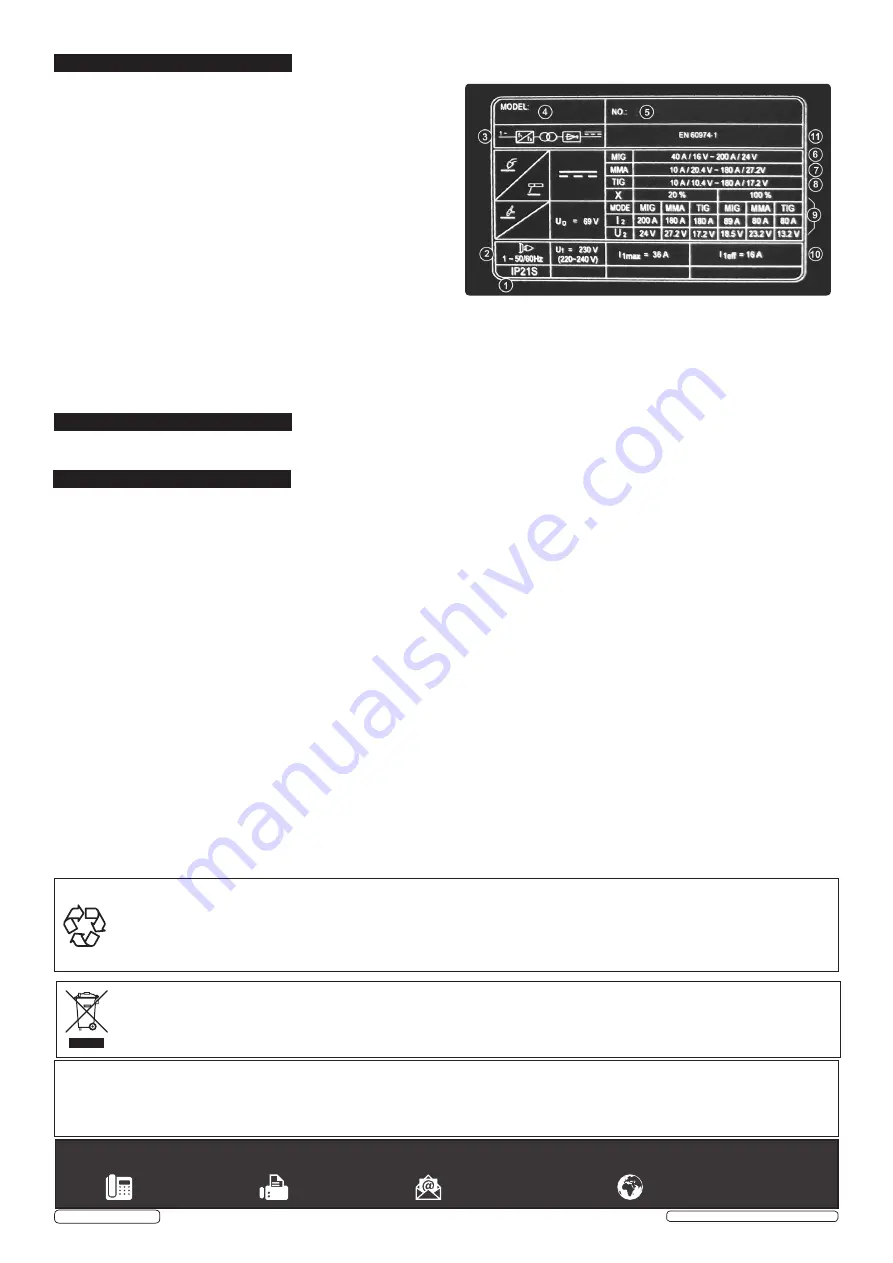
8. RATINGS PLATE
9. DUTY CYCLE
10. MAINTENANCE
The ratings plate on the inverter gives the following data:
1 -
Rating of internal protection provided by casing.
2 -
Symbol for power supply line: 1= Single-phase AC.
3 -
Symbol for internal structure of the welding machine.
4 -
Manufacturers Details and Model No.
5 -
Manufacturers Serial Number for welding machine identification.
6 -
MIG Output.
7-
MMA Output
8 -
TIG` Output
9 -
Power Supply
U
1
: Alternating voltage and power supply frequency of welding
machine. (allowed limit ± 10%)
I
1
max
: Maximum current absorbed by the line.
I
1
eff
: Effective current supplied.
10 -
Duty Cycle
Uº: Maximum no load voltage.
I², U²: Current and corresponding normalised voltage that the
welding machine can supply during welding.
X: Welding ratio based on a 10 minute duty cycle. 20% indicates 2
minutes welding and 8 minutes rest, 100% indicates continuous
welding.
11 -
The EUROPEAN standard relating to the safety and construction
of arc welding machines.
When the machine reaches the end of its duty cycle and overheats, the thermostatic switch opens to allow the internal components
to cool. This is denoted by the error page illuminating. Allow the machine to cool and resume use when the error warning clears.
10.1. WIRE FEED UNIT
Check the wire feed unit at regular intervals. The feed roller wire guide plays an important part in obtaining
consistent results. Poor wire feed affects welding. Clean the rollers weekly, especially the feed roller groove, removing all dust
deposits.
10.2. TORCH
Protect the torch cable assembly from mechanical wear. Clean the liner from the machine forwards by using compressed
air. If the liner is clogged it must be replaced.
10.3. CHANGING FEED ROLLER
(See Section 4.6.)
11.4. CONTACT TIP
The contact tip is a consumable item and must be replaced when the hole becomes enlarged or oval. The contact
tip
MUST
be kept free from spatter to ensure an unimpeded flow of gas. Refer to fig.9 and section 4.4.4 for removal and replacement.
10.5. GAS CUP
The gas cup must also be kept clean and free from spatter. Build up of spatter inside the gas cup can cause a short
circuit at the contact tip which will result in either the fuse blowing on the printed circuit card, or expensive machine repairs. To keep
the contact tip free from spatter, we recommend the use of Sealey anti-spatter spray (MIG/722308) available from your
Sealey Dealer.
10.6. REPLACING THE LINER
Wind the wire back on to the spool and secure it. Unscrew the torch from the machine and undo the brass
nut. The liner should now be visible. Pull it out and replace with a new one.
10.7
Remove the casing periodically and, with a low pressure air flow (max 1bar or 15psi), remove dust from inside the machine.
10.8.
Do not direct compressed air onto the electronic circuit boards, these should be cleaned with a very soft brush.
10.9.
Ensure that all electrical connections are tight and check the wiring for damage to the insulation.
10.10.
Ensure that the casing is correctly replaced and secured before attempting to use the inverter.
10.11.
Keep the outside of the machine clean by wiping with a soft, dry cloth.
For any other service or maintenance, contact your local Sealey service agent.
Sealey Group, Kempson Way, Suffolk Business Park, Bury St Edmunds, Suffolk. IP32 7AR
01284 757500
01284 703534
www.sealey.co.uk
WEEE REGULATIONS
Dispose of this product at the end of its working life in compliance with the EU Directive on Waste Electrical and Electronic Equipment
(WEEE). When the product is no longer required, it must be disposed of in an environmentally protective way. Contact your local solid
waste authority for recycling information.
Note
: It is our policy to continually improve products and as such we reserve the right to alter data, specifications and component parts without prior
notice.
Important
: No Liability is accepted for incorrect use of this product.
Warranty
: Guarantee is 12 months from purchase date, proof of which is required for any claim.
ENVIRONMENT PROTECTION
Recycle unwanted materials instead of disposing of them as waste. All tools, accessories and packaging should be sorted, taken to
a recycling centre and disposed of in a manner which is compatible with the environment. When the product becomes completely
unserviceable and requires disposal, drain any fluids (if applicable) into approved containers and dispose of the product and fluids
according to local regulations.
INVMIG200LCD ISSUE:1 - 11/08/17
Original Language Version
© Jack Sealey Limited


