4.1.
GAS SUPPLY
4.1.1.
ATTACHING THE REGULATOR.
(fig.3)
Whichever gas you are using it is advisable to
'crack' the cylinder valve before attaching the regulator. This means opening and closing the
valve very quickly in order to blow away any dust and dirt that may have accumulated in the
gas outlet. Stand to one side whilst doing this.
4.1.2.
CO² GAS.
Ensure that the threads on the gas bottle are undamaged and free of oil and grease
before attaching the regulator. (Oil or grease in the presence of high pressure gases can be
explosive.) Ensure that the regulator has an undamaged gasket fitted. The regulator will
screw directly to the threads on the gas bottle. Tighten with a wrench.
4.1.3.
ARGON GAS OR ARGON MIXTURES.
Cylinders containing argon gas and argon mixtures have
a female thread and will require the use of a Bull Nose Adaptor to attach the regulator to the
cylinder as indicated in fig.3. Ensure that the threads on the gas bottle are undamaged and free
of oil and grease before attaching the regulator. (Oil or grease in the presence of high
pressure gases can be explosive.) Fit the Bull Nose Adaptor to the cylinder first and tighten with a wrench.
4.1.4. Slide a hose clip over each end of the gas hose supplied. Push one end of the hose onto the regulator outlet and the other end over
the gas inlet spigot on the back of the welder. Tighten the clips to ensure a good seal.
4.1.5. Close the regulator valve by turning it anticlockwise before opening the cylinder valve. Stand to one side when opening.
4.1.6. Set the regulator flow rate to 5-8 litres/min depending on the material to be welded, and whether there are draughts which are strong
enough to disturb the gas flow.
c)
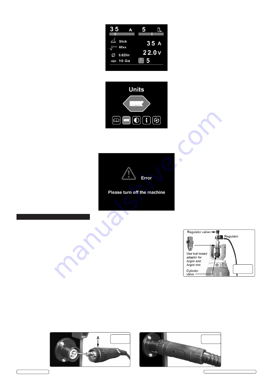
When Stick welding, user can set current, arc force parameter and hot start.
3.1.6.
Setting interface:
shows language setting, units setting, light setting, information and recover setting.
3.1.7.
Alarm interface:
shows the machine is overloaded and the internal temperature is too high. Weld output will turn off automatically but
the fan will still be working. When the internal temperature is decreased, the alarm interface will turn off and the machine will be ready to
weld.
4. PREPARATION
4.2.
CONNECTING THE TORCH CABLE TO THE WELDER.
Align the pins on the Euro connector with the socket on the welder front panel
as shown in fig.4. Push the connector into the socket and rotate the locking ring (A) clockwise so that it draws the plug into the socket as
shown in fig.5.
Note: damage to torches and cables is not covered by warranty.
fig.3
fig.4
fig.5
INVMIG200LCD ISSUE:1 - 11/08/17
Original Language Version
© Jack Sealey Limited


