3. ASSEMBLY
4. CONTROLS & SYMBOLS
Unpack the product and check contents. Should there be any damaged or missing parts contact your supplier immediately.
3.1.
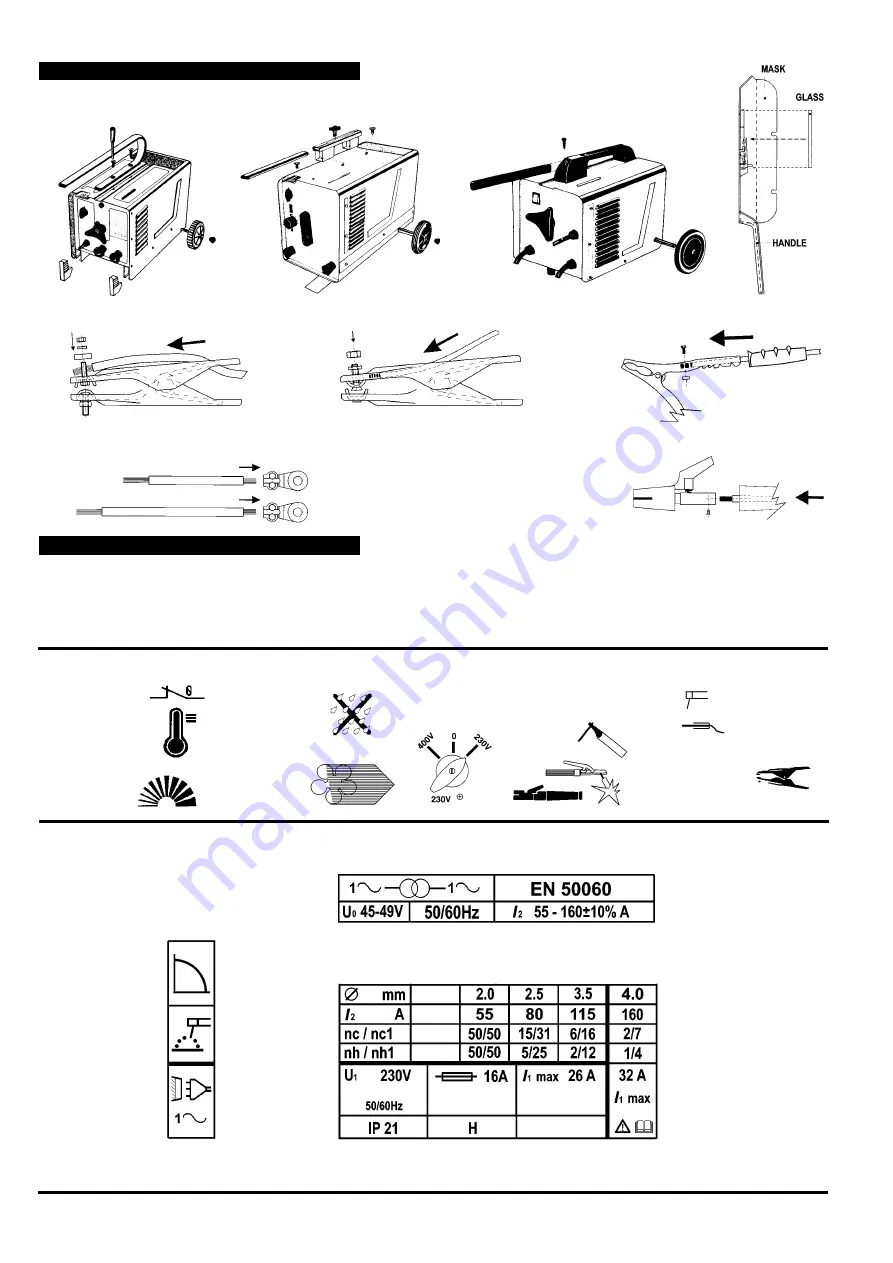
Where necessary assembly wheels, handle, feet etc (fig 1a,b,c) and fit the lens inside face mask (fig 2).
3.2. Where necessary assemble the work clamp supplied with your model to the cable associated with the work collet symbol as indicated below.
3.3. Where necessary assemble the electrode holder supplied with your model to the cable associated with the manual arc welding symbol.
(see fig.3). On models with terminal style connections assemble eyelets to cables as shown in fig.4.
The following is to assist you identify your models control panel symbols.
ELECTRO-FAN
Cools the
machine when
running.
THERMOSTATIC
PROTECTION
Lights up when the
machine overheats
and cuts out. The
machine can be used
again when cooled.
SWITCH
POSITION
settings
EARTH
CLAMP
REGULATION
SCALE
RAIN WARNING
SYMBOL
DO NOT
use the
machine in the
rain or snow.
ELECTRODE HOLDERS
various. The electrode holder
is connected to
the machine
via this
outlet,
Manual arc welder
Work Collet
4.1.
Introduction.
Your welder features either a single phase or a three phase transformer with a drooping characteristic suitable for welding with
an alternating current using stick electrodes with diameters from 1.5mm to the highest electrode diameter as described on the data table to
be found on the welders front panel or top cover. The welding current may be regulated by using the screw type stepless welding current
control. The value of the current (1
2
) may be read on the amp graduated scale, this corresponds to the voltage of the arc (U
2
) according to
the equation: U
2
= (18+0,041
2
) V (EN 50060).
Fig 2
Fig 4
Arc Welders - (0051) - (3) - 070601
Symbol for drooping
characteristic.
â
Indicates manual
arc welding with a
covered electrode.
â
Indicates an
alternating current
power supply and 1 to
3 phases as required
by the specification.
â
Diameter of
electrode.
â
Rated
â
welding current.
Rated no load
ã
voltage (min & max)
Welding power source symbol
showing single phase transformer.
ä
British Standard applying
to arc welders
ä
Frequency
ã
of alternating
current
Code letter for
ã
class of insulation.
Rated value of
supply voltage and
its frequency.
â
Max & min rated
ã
value for weld current
á
nh
= no. of electrodes
weldable between restart
and further thermal switch
interruption.
nh1
= no. of electrodes
weldable in one hour when
welder starts at thermal
steady state.
nc
= no. of electrodes
weldable starting at room
temperature until the
thermostat intervenes.
nc1
= no. of electrodes
weldable in one hour when
welder starts at room
á
temperature.
ã
Rated maximum
ã
supply currents
International
â
Standard relating
to moisture ingress
indicating degree of protection.
Mains fuse
required
GUIDE TO RATINGS
PLATE AND SYMBOLS
(For actual ratings of your model
refer to the front panel or top cover.)
FOR ANY FURTHER
CLARIFICATION OF
SYMBOLS REFER TO
BRITISH STANDARD
EN 50060
Fig 1a
Fig 1b
Fig 1c
Fig 3


