background image

YAK 3

Instruction Manual.

32

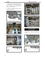
ATTACHMENT WING- FUSELAGE.

Then, install wing guns on the wings.


Wing bolt.

Receiver.

Battery.

Battery.

Summary of Contents for YAKOVLEV YAK 3 ARF

Page 1: ...ions Wingspan 63 0 in 160 cm Wing area 723 9 sq in 46 7sq dm Weight 11 5 lbs 5 2 kg Length 55 4 in 140 6 cm Engine 20cc Radio 7 channels with 9 servos Graphics and specifications may change without no...

Page 2: ...help you build a great flying aeroplane Please read this manual throughly before starting assembly of your YAK 3 Use the parts listing below to indentify all parts Please be aware that this aeroplane...

Page 3: ...ow plug to suit engine Propeller to suit engine Protective foam rubber for radio system Thin cyanoacrylate glue Medium cyanoacrylate glue 30 minute epoxy 5 minute epoxy Hand or electric drill Assorted...

Page 4: ...the aileron against the wing panel A gap of 1 64 or less should be maintained between the wing panel and aileron Hinge 4 Deflect the aileron and completely satu rate each hinge with thin C A glue The...

Page 5: ...eron from the wing panel Use caution not to crush the wing structure Work the aileron up and down sev eral times to work in the hinges and check for proper movement Note INSTALL THE AILERONS CONTROL H...

Page 6: ...ening in the mount The notch in the sides of the mount allow the servo lead to pass through Note to be convenience for trans ports you don t need to do this steps 1 Using a small weight Weighted fuel...

Page 7: ...connec tion so they cannot become unplugged 6 Secure the servo to the aileron hatch using Phillips screwdriver and the screws provided with the servo 7 Apply 1 2 drops of thin C A to each of the mount...

Page 8: ...tall it with four wood screws 2x10mm INSTALLING THE FLAP SERVO Repeat the procedure for the flap servo AILERON PUSHROD INSTALLATION Please see below pictures Use a felt tip pen to mark the wire where...

Page 9: ...keeper Snap keeper Servo arm Fuel tubing Hex Nut Nylon Snap keeper INSTALLING THE FLAP PUSHROD LIGHT COVER Repeat the procedure for the aileron pushrod 1 Locate the items necessary to install retracta...

Page 10: ...YAK 3 Instruction Manual 10 Mark Drill 3 5x20 mm 2 Install servo for Retractable landing gear A A 38mm M3 clevis M3 lock nut...

Page 11: ...NDING GEAR Electric retractable landing gear is not included in this kit however it is a very popular add on as optional If you want to use retracts in your YAK 3 we recom mend that you buy a good set...

Page 12: ...YAK 3 Instruction Manual 12 Drill...

Page 13: ...djust the size of the precut opening in the mount The notch in the sides of the mount allow the servo lead to pass through 1 Install the rubber grommets and brass collets onto all servos Test fit the...

Page 14: ...he servo arm as same as picture below Servo arm Adjustable servo connector Loctite secure Throttle servo arm INSTALLING THE STOPPER ASSEMBLY 1 Using a modeling knife carefully cut off the rear portion...

Page 15: ...he vent tube should rest just below the top of the tank It should not touch the top of the tank 6 When satisfied with the alignment of the stopper assembly tighten the 3 x 20mm ma chine screw until th...

Page 16: ...compartment Air should flow through easily Ignition Module ENGINE MOUNT INSTALLATION 1 Locate the items necessary to install the engine mount included with your model 4x30mm 2 Use four 4x30mm head bo...

Page 17: ...e pre drill 5 Slide the pushrod tube in the firewall and guide it through the fuel tank mount Use medium C A to glue the tube to the firewall and the fuel tank mount Machine screw M4x30mm Pushrod wire...

Page 18: ...d install the servo horn perpendiular to the servo center line 9 Movethethrottlesticktotheclosedpo sition and move the carburetor to closed Use a 2 5mm hex wrench to tighten the screw that secures the...

Page 19: ...and spinner in order to find the exact location of the cowl When satisfied with the cowl placement secure the cowl to the fuselage using masking tape Needle valve 3x10mm 2 Install the muffler and muf...

Page 20: ...es below 4 Attach the motor to the front of the electric motor box using four 4mm blind nut four M3x15mm hex head bolts to se cure the motor Please see picture shown M4x20mm Motor 110 2000 Watt Propel...

Page 21: ...ds from the speed control to the mo tor Make sure the leads will not interfere with the operation of the motor Speed control INSTALLING THE SPINNER The propeller should not touch any part of the spinn...

Page 22: ...izer at the trailing edge and place a mark Use a tri angle and extend this mark from back to front across the top of the stabilizer Also extend this mark down the back of the trailing edge of the stab...

Page 23: ...ilizer mounting platform sides in the fuselage Remove the covering from both the top and the bottom of the platform sides Epoxy 7 When you are sure that everything is aligned correctly mix up a genero...

Page 24: ...into the lower rear portion of the fu selage This slot accepts the lower rudder hinge Remove covering 2 Slide the vertical stabilizer into the slot in the top of the fuselage The rear edge of the stab...

Page 25: ...a thin layer to the mounting slot and to bottom of the vertical stabilizer mounting area Apply epoxy to the bot tom and top edges of the filler block and to the lower hinge also Set the stabilizer in...

Page 26: ...o each elevator control rod Thread the horns on until they are flush with the ends of the control rods 4 Elevator and rudder pushrods assem bly as pictures below Pen M2 clevis M2 lock nut 8mm 8mm Nylo...

Page 27: ...27 Pen 8mm MOUNTING THE TAIL WHEEL...

Page 28: ...YAK 3 Instruction Manual 28...

Page 29: ...29 PLASTIC PARTS WITH PANEL INSTRUCTIONS A C B A B C C A B C...

Page 30: ...YAK 3 Instruction Manual 30 B B B A C INSTALLATION PILOT AND CANOPY 1 Locate items necessary to install pilot seats...

Page 31: ...ontact exposing the bare wood Then permanently glue the canopy in place with epoxy glue or special canopy glue Epoxy 1 If all the decals are precut and ready to stick Please be certain the model is cl...

Page 32: ...YAK 3 Instruction Manual 32 ATTACHMENT WING FUSELAGE Then install wing guns on the wings Wing bolt Receiver Battery Battery...

Page 33: ...ore speed for take off and make it more difficult to slow down for landing Moving the balance aft makes the model more agile with a light er and snappier feel In any case please start at the location...

Page 34: ...YAK 3 Instruction Manual 34 160mm CONTROL THROWS Ailerons High Rate 15mm Low Rate 12mm Elevator High Rate 15mm Low Rate 12 mm Rudder High Rate 25mm Low Rate 20 mm...

Page 35: ...the right The right aileron should move up and the other aileron should move down If it does not flip the servo reversing switch on your transmitter to change the direction 1 Completely charge your tr...

Page 36: ...tory 12 101A Hamlet 4 Le Van Khuong Street Dong Thanh Ward Hoc Mon District Ho Chi Minh City Viet Nam Office 62 8 Ngo Tat To Street Ward 19 Binh Thanh District Ho Chi Minh City Viet Nam Phone 848 3711...

Reviews: