25
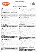
hen, use 7mm drill bit to enlarge the
holes on the electric motor box.
7
.
8
.
9
.
6
.
7mm.
Blind nut.
M5x20mm.
Epoxy.
Attach the speed control to the side
of the motor box using two-sided tape
and tie wraps. Connect the appropriate
leads from the speed control to the mo-
tor. Make sure the leads will not interfere
with the operation of the motor.
11
.
12
.
10
.
180mm.
Summary of Contents for SEA 362
Page 5: ...5 12 13 14 15 17 16 18 19 Epoxy ...
Page 11: ...11 7 6 8 9 LANDING GEAR INSTALLATION Locate items needed for landing gear installation 1 2 3 ...
Page 13: ...13 12 13 16 15 17 18 14 19 3x4mm ...
Page 15: ...15 1 2 5 4 6 7 3 8 3x4mm ...
Page 17: ...17 17 18 21 20 22 23 19 24 3x20mm ...
Page 21: ...21 M5x110mm 180mm 7 9 12 10 8 Ignition Modude Pushrod wire 11 13 14 ...
Page 27: ...27 3 4 5 1 INSTALL ELEVATOR CONTROL HORN Fiberglass control horn 2 Epoxy Epoxy 3 4 5 Epoxy ...
Page 35: ...35 4 5 6 7 8 9 2 3 ...
Page 37: ...37 20 21 22 23 24 25 19 18 Epoxy ...
Page 39: ...39 36 37 38 39 40 41 2x6mm 34 35 2x6mm ...
Page 41: ...41 10 11 12 16 13 14 15 Epoxy 9 ...
Page 45: ...45 12 13 10 11 16 17 14 15 4x25mm ...
Page 47: ...47 29 26 27 28 2x8mm 32 30 31 1 ANTENNA INSTALLATION Parts requirement See pictures below ...