background image

Medalist 1721, 1010, Rev. B

7

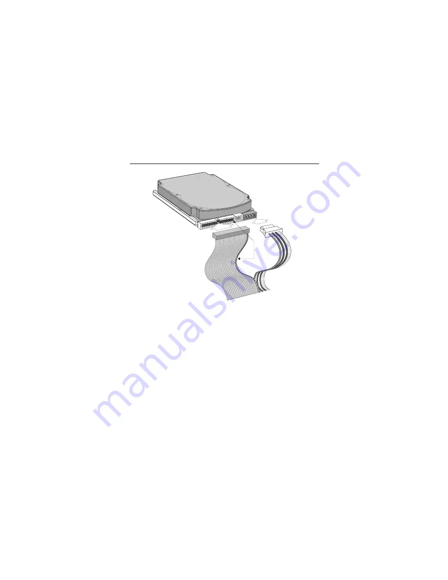
Figure 4. Cable connectors

Note. If you are mounting the drive in a 5.25-inch drive bay, you

need a mounting adapter or frame kit. Contact your com-
puter dealer. Some computers also require drive mount-
ing rails, which can be obtained from your distributor or
computer manufacturer.

5. Attach a power cable to each drive. If your computer does not

have an unused power connector, you can purchase a Y-
shaped power cable from your computer dealer.

6. Check all cable connections and then replace your computer

cover. Continue to “Configuring your computer.”

Pin 1

Interface
connector

Power
connector

Summary of Contents for Medalist 1010

Page 1: ... Medalist 1721 ST31721A Medalist 1010 ST31010A for ATA IDE Compatible PCs Installation Guide ...

Page 2: ... Seagate Technology and the Seagate logo are regis tered trademarks of Seagate Technology Inc Medalist DiscWiz ard SeaFAX SeaFONE SeaBOARD and SeaTDD are either trademarks or registered trademarks of Seagate Technology Inc or one of its subsidiaries All other trademarks or registered trademarks are the property of their respective owners ...

Page 3: ...drive capacity limitations 10 Partitioning and formatting your drive 12 Installation using Disk Manager 13 Windows 95 or Windows 98 installation 14 Standard DOS installation 15 Additional installation options 17 Non ATA compatible slave jumper 17 Cable select jumper 18 Advanced Disk Manager options 19 Troubleshooting 22 Seagate Technology support services 28 Storing and shipping your drive 34 iii ...

Page 4: ...0 Medalist 1721 1010 Rev B iv ...

Page 5: ...you are mounting this 3 5 inch drive in a 5 25 inch drive bay you need a mounting adapter or frame kit Also you may need drive mounting rails if your drive bay is not designed for direct mounting Before you begin Make sure your computer is turned off before you open the case Read the handling precautions following and inspect the drive to make sure that it is not damaged Save your foam lined Seaga...

Page 6: ... Protect your drive from static discharge by making sure you are well grounded before touching the drive We recommend wearing a grounded wrist strap throughout the installation process Do not touch the connectors or any part of the printed cir cuit board Always handle the drive by its edges or frame Do not apply pressure or attach labels to the circuit board or the top of the drive ...

Page 7: ...ive you must configure one drive as a mas ter and the other as a slave To configure the drive as a master or one drive only Place a jumper on pins 5 and 6 see Figure 1 on page 4 The master drive usually defaults to being the boot drive drive C from which the computer loads system software when it first starts up To configure the drive as a slave Remove all the jumpers If you need to change the jum...

Page 8: ...4 Medalist 1721 1010 Rev B Figure 1 Master and slave jumper settings pin 1 ATA interface connector 1 3 5 2 4 6 Slave Master or single drive 4 pin power connector ...
Page 9: ...e no more than 18 inches 457 mm long 2 Thread the interface cable through the drive bay and attach the connector at the end of the interface cable to your new drive Note If you have two drives attach the second drive to the sec ond connector Figure 2 Attaching the cables Caution To avoid possible damage to your system make sure to align pin 1 on the host adapter or mother board with pin 1 on your ...

Page 10: ...y into the drive bay Secure the drive with four 6 32 UNC mounting screws in either the side mounting holes or the bottom mounting holes Insert the screws no more than 0 22 inch 5 58 mm into the bottom mounting holes and no more than 0 20 inch 5 0 mm into the side mounting holes Caution To avoid possible damage to the drive do not overtighten the screws or use metric screws ...

Page 11: ...require drive mount ing rails which can be obtained from your distributor or computer manufacturer 5 Attach a power cable to each drive If your computer does not have an unused power connector you can purchase a Y shaped power cable from your computer dealer 6 Check all cable connections and then replace your computer cover Continue to Configuring your computer Pin 1 Interface connector Power conn...
Page 12: ...am 2 Enable LBA mode if it is available Many BIOS use the logical block addressing LBA mode to access drives with capacities greater than 528 Mbytes 3 If your BIOS provides automatic drive detection an Auto drive type select this option This allows your computer to configure itself automatically for your new drive If your BIOS does not provide automatic drive detection select User defined drive se...

Page 13: ...built before mid 1994 you probably will not be able to access the full capacity of your new drive unless you use Disk Manager See page 13 for information on Installation using Disk Manager If you do not want to use Disk Manager you can use the stan dard DOS commands to partition and format your drive as described on page 15 Drive Cylinders Heads Sectors ST31721A LBA addressing CHS addressing 826 3...

Page 14: ...byte limit The BIOS in some older computers cannot accommodate drives with capacities greater than 528 Mbytes Seagate provides free Disk Manager software with your drive to overcome this limita tion Alternatively you can purchase a hard drive controller or a BIOS upgrade that supports drives with capacities greater than 528 Mbytes The 32 bit disk access feature in Windows 3 1 does not work with dr...

Page 15: ...can Megatrends AMI 1 800 828 9264 http www megatrends com Award Software International Inc 1 800 800 2467 http www award com Microid Research Mr BIOS 1 978 686 6468 Upgrades from Unicore Software http www mrbios com Phoenix Technologies Ltd 1 800 767 5465 Upgrades from Microfirmware http www ptltd com SystemSoft http www systemsoft com ...

Page 16: ...g Windows 95 or Windows 98 Boot your computer from the Windows 95 or Windows 98 startup diskette with the CD ROM loaded Note the drive letter for your CD ROM device At the A prompt type x setup where x is the letter of your CD ROM drive Continue with the Windows setup instructions Two drives You can use Disk Manager to install an additional drive See Installation using Disk Manager on page 13 To a...

Page 17: ...e and your existing hard drive if any If any hard drive is not recognized exit Disk Manager and turn off your computer Check all cables jumpers and BIOS settings Then start at Step 1 to run Disk Manager again 4 If Disk Manager recognizes all your drives select the drive you want to install and press ENTER Disk Manager partitions and formats the drive Note If your computer cannot accommodate hard d...

Page 18: ...oot your computer from the Windows 95 or Windows 98 startup diskette with the CD ROM loaded 2 Note the drive letter for your CD ROM device 3 At the A prompt type x setup where x is the letter of your CD ROM drive 4 Continue with the Windows setup instructions You re Done ...

Page 19: ...t a bootable DOS diskette into your diskette drive and restart your computer Seagate recommends using DOS Ver sion 5 0 or greater 2 Insert a DOS program diskette that has the FDISK EXE and FORMAT COM programs into your diskette drive At the A prompt type FDISK and press ENTER 3 If you have two hard drives installed the FDISK menu dis plays five options Option five allows you to select the drive yo...

Page 20: ...re to use the correct drive letters so that you do not format a drive that already contains data At the A prompt type format x s where x is the letter of your first new partition Repeat the format process for all the new par titions you have created Note From FDISK in Windows 95 or Windows 98 it is not nec essary to add the s to the format command because these system files are automatically added...

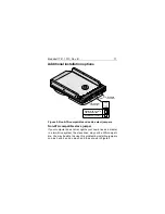
Page 21: ...omputer does not recognize your new drive as a master in a two drive system the slave drive may not be ATA compati ble You may be able to solve this problem by installing jumpers on pins 3 and 4 and on pins 5 and 6 as shown in Figure 5 pin 1 ATA interface connector 1 3 5 2 4 6 Master with non ATA compatible slave Enable cable select 4 pin power connector ...
Page 22: ...ace cables that have the line to pin 28 the Cable Select pin removed or cut at one connector The connector that has pin 28 disabled is used for the slave drive See your computer manual to determine whether your computer supports this feature To configure your Seagate drive for cable select place a jumper on pins 3 and 4 as shown in Figure 5 ...

Page 23: ... DDO must load into memory before the operating system loads This occurs auto matically when you boot from your hard drive drive C However if you boot from a diskette the DDO will not be loaded and you will not be able to access your hard drive The following proce dure allows you to boot from a diskette and still access your hard drive 1 Boot the computer from the hard disc with no diskette in the...

Page 24: ...the dynamic drive overlay If Disk Manager installs a dynamic drive overlay DDO and you do not need this software to access the full capacity of your drive you can remove the dynamic drive overlay without losing your data However you will lose access to the full capacity of your drive unless you have another method for accessing high capacity drives see Addressing drive capacity limitations on page...

Page 25: ... finished exit Disk Man ager 8 Remove the diskette and reboot the computer Enter your system setup program see your system manual for details 9 Configure the hard drive with the Cylinder Head Sector parameters shown for your drive in the table on page 9 Save your changes and exit the system setup program 10 When your computer has rebooted insert the Disk Manager diskette into drive A 11 Type A DM ...

Page 26: ...herboard and secured with mounting screws Check all connectors and cables Make sure all ribbon and power cables are securely connected Ribbon cables are eas ily damaged especially at the connector Try a new cable that you know is good Make sure no connector pins are bent Ver ify that pin 1 on the interface cable is aligned with pin 1 on the drive and host adapter see Figure 2 on page 5 Verify jump...

Page 27: ...prob lem persists follow these guidelines for troubleshooting specific cases Caution To avoid electrostatic discharge damage to your computer or hard drive make sure you are well grounded before touching the drive cable connector or jumpers The screen remains blank when you power up the system If the steps listed above do not remedy this problem try the fol lowing Make sure the monitor is plugged ...

Page 28: ...ng the CTRL ALT and DELETE keys simultaneously If the drive is recognized after you reboot the system the computer BIOS test may be completing before the drive is ready One solution is to slow the processor speed during startup If your computer has a turbo switch set it to slow speed before turning the computer on If there is no turbo switch you may be able to use keyboard commands see your comput...

Page 29: ...e Booting with a Diskette instruc tions under Advanced Disk Manager Options on page 19 The dealer partitioned and formatted the drive for you in the store but the drive does not respond when you install it Reboot the computer and make sure the drive spins up Check all cables Make sure the power supply is adequate for system needs Make sure the DOS or Windows version the dealer used to partition an...

Page 30: ...one The system error message Drive not Ready appears Check all cable connections Make sure pin 1 of the drive is connected to pin 1 of the hard disc controller or host adapter Make sure the power supply is adequate for system needs Reboot the computer and make sure the drive spins up The FDISK error message No Fixed Disk Present appears Make sure the power supply is adequate for system needs Verif...

Page 31: ...ual logical drives you may need to make the partitions smaller to access the full drive capacity If your computer supports LBA mode you may need to enable LBA mode in the system setup program to access the full capacity of the drive Refer to your computer s reference guide to find out how to enable LBA The DOS message Disk Boot Failure Non System Disk or No ROM Basic SYSTEM HALTED appears Reinstal...

Page 32: ...ttp www seagate com support email email_disc_support shtml or DiscSupport Seagate com Tape http www seagate com support email email_tape_support shtml or TapeSupport Seagate com SeaBOARD is a computer bulletin board system that contains information about Seagate disc and tape drive products and is available 24 hours daily Set your communications software to eight data bits no parity and one stop b...

Page 33: ...ication or computer system Seagate Express You can purchase select tape products and tape accessories through Seagate Express 24 hours daily by calling 1 800 531 0968 or by faxing your order to 1 972 481 4812 Technical support If you need help installing your drive consult your dealer Deal ers are familiar with their unique system configurations and can help you with system conflicts and other tec...

Page 34: ...ther customers should contact their place of purchase Authorized Service Centers If you live outside the US you can contact an Authorized Service Center for service or repair USA Canada Latin America Support Services Presales Support Disc 1 877 271 3285 or FAX 1 405 936 1683 1 405 936 1210 Tape 1 800 626 6637 or FAX 1 714 641 2410 1 714 641 2500 Technical Support SeaFONE 1 800 SEAGATE or 1 405 936...

Page 35: ...For European customer support dial the toll free number for your specific country for presales support technical support SeaFAX and warranty repair If your country is not listed here dial our European call center at 31 20 316 7222 from 8 30 A M to 5 00 P M European central time Monday through Friday The European call center is located in Amsterdam The Netherlands Call Center Austria 0 800 20 12 90...

Page 36: ...For presales technical support warranty repair and FAX ser vices in Africa and the Middle East dial our European call center at 31 20 316 7222 from 8 30 A M to 5 00 P M European central time Monday through Friday or send a FAX to 31 20 653 3513 The European call center is located in Amsterdam The Netherlands Asia Pacific East Support Services Technical Support Australia 61 2 9725 3366 FAX 61 2 972...

Page 37: ...Medalist 1721 1010 Rev B 33 SeaFAX Australia 61 2 9756 5170 Warranty Repair Japan 81 3 5462 2904 FAX 81 3 5462 2979 Asia Pacific and 65 485 3595 FAX 65 488 7503 Australia ...

Page 38: ...er voids the warranty Call your authorized Seagate distributor for information on pack ing materials Figure 6 shows how a drive fits in an approved sin gle pack box including the packing materials Note Back up the data on your drive before shipping the drive Seagate assumes no responsibility for data lost during shipping or drive repair Figure 6 Seagate drive and approved packing materials Foam An...

Page 39: ...mpatibility Directive 89 336 EEC of 03 May 1989 as amended by Directive 92 31 EEC of 28 April 1992 and Directive 93 68 EEC of 22 July 1993 Compliance of this drive as a system component was con firmed with a test system We cannot guarantee that your system will comply The drive is not meant for external use without prop erly designed enclosure shielded I O cable etc Sicherheitsanleitung 1 Das Gerr...

Page 40: ...le Arbeiten auf dem Fest platte dürfen nur von Ausgebildetem Servicepersonal durchgeführt werden Bitte entfernen Sie nicht die Aufschriftens childer des Laufwerkes 6 Der Einbau des Laufwerkes muss den Anforderungen gemäss DIN IEC 950 VDE 0805 05 90 entsprechen ...

Page 41: ...Medalist 1721 1010 Rev B 37 ...

Page 42: ...38 Medalist 1721 1010 Rev B Seagate Technology Inc 920 Disc Drive Scotts Valley CA 95066 4544 USA Publication Number 21200092 001 Rev B Printed in USA ...

Reviews: