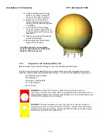
background image

9711-44 Ku-Band TXRX 

Installation (144” Radome) 


3-35 

If your modem cannot use the Modem Console Port connection you will have to 
provide a transmit inhibit output from the ACU by connecting a SW2 wire connection 
to the modem to comply with FCC Order 04-286 and WRC-03 Resolution 902


Dual or Quad Antenna Arbitrator coax switches in dual antenna configurations.  The coax 
switches select which antenna is feeding signal to the below decks equipment. 


Mute the Transmit output of the Satellite Modem used in TX/RX antenna configurations 
when the antenna is positioned where people may be harmed by the transmit power 

emanating from the antenna (RF Radiation Hazard).   


Mute the Transmit output of the Satellite Modem used in TX/RX antenna configurations 
when the antenna is mispointed by 0.5 degrees, or more, and keep it muted until the 

antenna has been within 0.2 degrees of peak pointing to the satellite for a minimum of 5 

seconds  (FCC part 25.221 & 25.222 TX Mute requirement).   

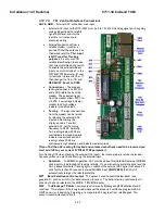
3.10.7.5.


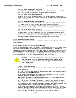
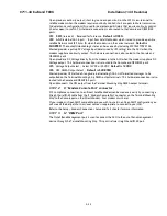
TS2  Synchro Gyro Compass Input.   

Use the R1, R2, S1, S2 and S3 screw terminals to connect the Synchro Gyro Compass to the ACU.  

3.10.7.6.


TS3  Step-By-Step (SBS) Gyrocompass Input.   

Use the COM, A, B and C screw terminals to connect the SBS Gyrocompass to the ACU.  Some SBS 

Gyro distribution boxes have terminals which are labeled S1, S2 & S3 instead of A, B and C.  

3.10.7.7.


TS4 Power 


VREG 

Screw terminal is used to provide a regulated DC operating voltage to ancillary 

equipment.  Voltage out is dependent upon which terminal mounting strip assembly is 

provided.  126865-1 supplies 8Vdc @ 1Amp, while the 126865-2 assembly supplies 5Vdc 

@ 2Amps.


GND 

Screw terminal is the ground reference for the regulated and unregulated power 

terminals.


12/24 

Screw terminal is commonly used to provide operating voltage to an external GPS, 

Dual Antenna Arbitrator or other below decks tone generators or switches.  Voltage output 

is based on the T.M.S assemblies JP5 jumper settings. 

3.10.7.8.


TS5 NMEA A/B, GPS output.   


RxA- and RxA+- screw terminals, which are defined as the NMEA A connection is used to 

connect to the ships Gyro Compass (Heading).  The NMEA0183 compliant inputs are then 
connected via a 9 pin ribbon cable to the ACU’s J2 NMEA communications port.  A GPS 

(Latitude and Longitude) input may also be connected, but is not required because there is 
a GPS device already installed in your antenna..  

NOTE:


If you connect a ships GPS to the 

terminal mounting strip, you 

MUST

 disconnect the GPS antenna on the antenna 

pedestal.


RxB- and RxB+ screw terminals, which are defined as the NMEA B connection is used to 
connect to the ships Gyro Compass (Heading).  The NMEA0183 compliant inputs are then 

connected via a 9 pin ribbon cable to the ACU’s J2 NMEA communications port.  A GPS 

(Latitude and Longitude) input may also be connected, but is not required because there is 

a GPS device already installed in your antenna. 


TxA-  screw terminal is used to provide a Pseudo GPS (GGA and GLL formats) output to 

other system components such as a Satellite Modem.   

3.10.8.


Other BDE connections   

Connect your other Below Decks Equipment (ie, telephone, fax machine  and computer equipment) to 

complete your configuration.   

3.11.


Final Checks 

3.11.1.


Visual/Electrical inspection 

Do a visual inspection of your work to assure that everything is connected properly and all cables/wires are 

secured. 

Summary of Contents for 9711-44 KU-BAND TX/RX

Page 1: ...to be used with transmit receive equipment manufactured by others Refer to the documentation supplied by the manufacturer which will describe potential hazards including exposure to RF radiation associated with the improper use of the transmit receive equipment Note that the transmit receive equipment will operate independently of the stabilized antenna system Prior to work on the stabilized anten...

Page 2: ...onnected to the modem the automatic cessation of transmission requirements of the 2009 version of FCC 47 C F R 25 222 Please refer to the declaration included in this manual Copyright Notice Copyright 2013 Sea Tel Inc All Rights Reserved The information contained in this document is proprietary to Sea Tel Inc This document may not be reproduced or distributed in any form without prior written cons...

Page 3: ......

Page 4: ... limited to 21 6 dBW 4kHz 0 9 Meter Ku Band Model 3612 is limited to 20 3 dBW 4kHz 1 0 Meter Ku Band Models 4003 4006 4009 4010 are limited to 16 3 dBW 4kHz 1 0 Meter Ku Band Model 4012 is limited to 16 6 dBW 4kHz 1 2 Meter Ku Band Models 4996 5009 5010 5012 are limited to 14 0 dBW 4kHz 1 5 Meter Ku Band Models 6006 6009 6012 are limited to 14 0 dBW 4kHz 2 4 Meter Ku Band Models 9797 and 9711QOR a...

Page 5: ... 2 5 4 Truss Mast 2 5 2 6 SAFE ACCESS TO THE ADE 2 5 2 7 BELOW DECKS EQUIPMENT LOCATION 2 5 2 8 CABLES 2 6 2 8 1 ADE BDE Coaxial Cables 2 6 2 8 2 Antenna Power Cable 2 6 2 8 3 Air Conditioner Power Cable 2 6 2 8 4 ACU Power Cable Outlet 2 7 2 8 5 Gyro Compass Cable 2 7 3 INSTALLATION 144 RADOME 3 1 3 1 GENERAL CAUTIONS WARNINGS 3 1 3 2 PREPARATION 3 2 3 3 OPENING YOUR CRATES 3 2 3 3 1 Location of ...

Page 6: ...Connections 3 31 3 10 6 Radio Control Serial Cable 3 32 3 10 7 Terminal Mounting Strip TMS Connections 3 32 3 10 8 Other BDE connections 3 35 3 11 FINAL CHECKS 3 35 3 11 1 Visual Electrical inspection 3 35 3 11 2 Electrical Double check wiring connections 3 36 3 12 POWER UP 3 36 3 13 CABLE TERMINATIONS 3 36 3 13 1 At The Radome 3 36 3 13 2 ACU TMS 3 36 3 13 3 Other BDE 3 36 3 14 FINAL ASSEMBLY 3 3...

Page 7: ...3 System Configuration 4 36 4 9 4 Installing the Below Deck Equipment 4 36 4 10 CONNECTING THE BELOW DECKS EQUIPMENT 4 37 4 10 1 Connecting the ADE AC Power Cable 4 37 4 10 2 Connecting the BDE AC Power Cables 4 37 4 10 3 Connecting the ADE IF Coaxes 4 37 4 10 4 Connect the Modem TXIF Coax 4 37 4 10 5 Antenna Control Unit Connections 4 37 4 10 6 Radio Control Serial Cable 4 38 4 10 7 Terminal Moun...

Page 8: ...E FLAG OFFSET 9 1 9 1 ELECTRONIC CALIBRATION OF RELATIVE ANTENNA POSITION HOME FLAG OFFSET 9 1 9 1 1 You Found a Large AZ TRIM value 9 1 9 1 2 You Observe Home Pointing is LEFT of the Bow line 9 2 9 1 3 You Observe Home Pointing is RIGHT of the Bow line 9 2 9 1 4 To Enter the HFO value in the DAC_2202 9 3 10 SETUP TARGETING 10 1 10 1 AUTO TRIM 10 1 10 2 MANUALLY OPTIMIZING TARGETING 10 1 10 3 EL T...

Page 9: ... 7 14 SETUP OPTIMIZING KU BAND POLARITY AND CROSS POL ISOLATION 14 1 14 1 POLARITY ANGLE POLANG PARAMETERS 14 1 14 2 OPTIMIZING AUTO POLARIZATION ON RECEIVE SIGNAL 14 1 14 3 OPTIMIZING AUTO POLARIZATION CROSS POL ISOLATION 14 2 14 4 SAVE NEW PARAMETERS 14 2 15 SETUP OTHER PARAMETERS 15 1 15 1 SETUP PARAMETER DISPLAY AND ENTRY MENUS 15 1 15 2 5V OFFSET SCALE 15 1 15 3 REMOTE COMMAND 15 1 15 4 REMOT...

Page 10: ...ON FAULTS 19 8 19 7 1 400MHz Modem Queries 19 8 19 7 2 Modem Query Methods 19 8 19 7 3 Isolating a 400 MHz Modem Fault Procedure 19 10 19 8 INSTALLING AND CALIBRATING THE KU BAND CO POL CROSS POL FEED 19 13 19 8 1 Installing the Ku Band Co Pol Cross Pol Feed Assembly 19 13 19 8 2 Calibrating the Ku Band Co Pol Cross Pol Feed Assembly 19 18 19 9 PEDESTAL CONTROL UNIT CONFIGURATION MK2 19 21 19 9 1 ...

Page 11: ...er Furnished 22 9 22 4 3 Multi conductor Cables Customer Furnished 22 9 22 4 4 AC Power Cable Pedestal Rf Equipment 22 9 22 4 5 AC Power Cable Optional Marine Air Conditioner 22 9 22 4 6 Gyro Compass Interface Cable Customer Furnished 22 10 23 DRAWINGS 23 1 23 1 9711 44 MODEL SPECIFIC DRAWINGS 23 1 23 2 9711 GENERAL DRAWINGS 23 1 ...

Page 12: ...Table of Contents xii This Page Intentionally Left Blank ...

Page 13: ...hich has adequate signal coverage in your current geographic area This input will be distributed to your satellite modem and then to all of your other below decks computer fax and telephone equipment 1 3 Other Inputs to the System Multi conductor cables from Ship s Gyro Compass GPS phone fax and computer equipment may be connected in the system 1 4 System Components The Series 11 TXRX system consi...

Page 14: ...tenna A AND ACU B to be able to control Antenna B and ONLY Antenna B You will program the blockage zone s for each of the two antennas refer to Setup Blockage Zones The blockage output from the ACU is fed to the Terminal Mounting Strip so that the output of each ACU can be connected to the arbitrator panel to control it The blockage output is available on SW2 terminal of the Terminal Mounting Stri...

Page 15: ...tor installation instructions to balance the TX and RX signal levels between the two antennas 1 7 Open Antenna Modem Interface Protocol OpenAMIP Specification 1 7 1 Overview OpenAMIPTM an ASCII message based protocol invented and Trademarked by iDirect is a specification for the interchange of information between an antenna controller and a satellite modem This protocol allows the satellite modem ...

Page 16: ... or DAC 2302 Any Satellite modem manufacturer that is compatible with OpenAMIPTM CAT5 Patch cable 1 7 2 2 Software Sea Tel model DAC 2202 ACU software version 6 06 or greater CommIF module software version 1 10f or greater Sea Tel model DAC 2302 ACU software version 7 06 or greater CommIF module software version 1 10f or greater ...

Page 17: ...d be mounted more than 2 5 meters 8 feet away from any GPS receiver antennae Another consideration for any satellite antenna mounting is multi path signals reflection of the satellite signal off of nearby surfaces arriving out of phase with the direct signal from the satellite to the antenna This is particularly a problem for the onboard GPS and or the GPS based satellite compass The ADE and the B...

Page 18: ... personnel safety when entering the hatch of the radome The recommended cable passage is through the bottom near center of the radome base down through the ADE support pedestal if used through the deck and into the interior of the ship 2 3 3 Sizing of the support pedestal The following should be taken into account when choosing the height of a mounting support stand 1 The height of the pedestal sh...

Page 19: ...comes a force trying to pull the ADE to the side The tangential acceleration has an effect on both the strength of the ADE pedestal and the tracking accuracy of the control algorithm The effect of tangential acceleration is felt by the structure of the ADE before it truly affects the tracking accuracy For instance Sea Tel normally accepts that a tracking error of 0 1 degrees RMS at 0 5 G to be wit...

Page 20: ...st platform the ADE is mounted on should be checked for torsional vibration about the centerline of the mast and the orthogonal centerline of the platform If the estimated natural frequency of the mast or platform is less than 35 Hertz the mast or platform should be stiffened by the addition of deeper gussets under the platform or behind the mast 2 5 2 Raked Masts Raked masts are found on vessels ...

Page 21: ...ructure of the platform In general the following guidelines apply when determining the adequate support for mounting an antenna on a truss mast 1 Antenna ADE pedestal gussets should align with platform stiffeners which are at least 200 millimeters in depth and 10 millimeters in thickness 2 When possible the antenna ADE pedestal column should align with a vertical truss support 3 For every 100 kilo...

Page 22: ...ble welded penetrations that must be pressure tested Always use good quality connectors that are designed to fit properly on the cables you are using Poor quality connectors have higher loss can allow noise into the cable are easily damaged or fail prematurely In as much as is possible don t lay the coaxes on power cables Try to have some separation from Inmarsat GPS cables that are also passing L...

Page 23: ...of IEC 60092 350 and 351 in so far as practicable 2 8 5 Gyro Compass Cable Use good quality shielded cables twisted pairs individually foil wrapped outer foil with braid overall is best You only need 2 wire for NMEA signal 4 wire for Step By Step and 5 wire for Synchro always use shielded cable Be cautious of length and gauge of the run for voltage loss issues 2 9 Grounding Refer to the Installati...

Page 24: ...Site Survey 9711 44 Ku Band TXRX 2 8 This Page Intentionally Left Blank ...

Page 25: ...ts 2760 Permanent strength for up to 1 diameter fasteners 290 Wicking High strength for fasteners which are already assembled WARNING Hoisting with other than a webbed four part sling may result in catastrophic crushing of the radome Refer to the specifications and drawings for the fully assembled weight of your model Antenna Radome and assure that equipment used to lift hoist this system is rated...

Page 26: ...t is recommended that you do not unpack the crates until you are ready to sub assemble and install the equipment Assure that you have a large flat level open area to sub assembly the baseframe pedestal dish feed and the upper lower sections of the radome This area should be clean and free of debris refer to the Installation chapters of Antenna and Antenna Control Unit manuals We recommend that you...

Page 27: ...bolts 3 4 socket around the bottom of that secure the outer frame to the bottom section of the crate and lift the outer frame off 3 Remove the plastic covering Feed Assembly some systems have multiple feeds Waveguide some systems and the Feed Struts are hidden by the reflector in this picture See steps 4 6 below Reflector shown in the raised position Base Frame Legs Brace Feet and hardware 4 Feed ...

Page 28: ... in the Pedestal Crate 3 3 3 Pedestal Crate We recommend that you place the Pedestal Crate in the area that you have chosen to assembly it 1 This is the Pedestal crate 2 Remove the outer frame top and sides of the crate by removing the Philips head screws placed around the bottom of that secure the outer frame to the bottom section of the crate and lift the outer frame off 3 Remove the plastic cov...

Page 29: ... with the Hardware and Miscellaneous Box Stage these items in the location where the Pedestal will be assembled NOTE Some systems may have lager groups of assembled counterweight on the pallet 3 3 4 Radome Crate We recommend that you place the Radome Crate in the area that you have chosen to assemble the Radome onto the base frame 1 This is the Radome crate 2 Remove the clips around the removable ...

Page 30: ...ocated on this crate The Reflector the Boxes containing the Feed LNB Assembly Assemblies if two along with the Feed Struts and Hardware Kit are located in this crate If there are two Feed LNB units they will each be in separate boxes Unpacking the Base Fame and Reflector 1 Open the crate to expose the contents as described above 2 Remove the lower lag bolts from the L brackets left and right that ...

Page 31: ...to support the structure in the raised position 5 Cut the 2 metal bands holding the base frame in place 6 Remove the base frame by hand or with a forklift out from under the reflector support structure 7 Move the base frame to the location where it will be assembled 8 Cut the straps that restrain the Base Frame Legs Braces Feet and Hardware Kit Box 9 Move these items to the area where the base fra...

Page 32: ...d LNB Box Contains Feed Assembly LNB Feed Flex Waveguide and Coaxial Cables on the pallet 13 Keep the Feed assembly in this area 14 If provided in this crate cut the tie wraps that hold the Wave Guide Box contains the Flex Waveguide and Coaxial Cable on the crate 15 Keep the Waveguide box in this area 16 Install the feed struts one at a time to the reflector aligning the labels on the end of the f...

Page 33: ...al 25 Keep any additional Feed assembly ies in this area with the reflector 26 Keep the Waveguide box in this area until you are ready to install the reflector on the Pedestal Note You will install the reflector later in the installation instructions 3 5 Unpacking the Pedestal Crate The Pedestal crate contains the Pedestal Assembly Spider DAC BDE box RF units Wave Guide boxes Hardware Kits and the...

Page 34: ...e this item in the location where the Base Frame will be assembled 8 Remove the plastic covering over the Pedestal Important It is good practice to secure the pedestal with lifting harnesses prior to removing the bolts in the subsequent steps First attach 2 lifting straps under the cross level beam on the pedestal Assure that no cables on the front or back side of the cross level beam are pinched ...

Page 35: ...e of the crate There is no longer any need to reach under the pallet to hold nuts while the bolt is being removed 13 Refer to the Installation chapter of the Antenna manual for pedestal assembly instructions 14 After removing these 8 bolts the Pedestal Assembly is free to be removed from the crate 15 Use a crane or other suitable lifting apparatus to lift the pedestal off of the crate and relocate...

Page 36: ...ad this entire assembly procedure before beginning Refer to the System Block diagram General Assembly Baseframe Assembly Radome Assembly and Radome Installation Arrangement drawings for your system Select a secure assembly site that provides enough area to work with the large radome panels while sub assembling the baseframe sections of the radome Antenna Pedestal and Reflector Feed The area should...

Page 37: ...me base frame on temporary support blocks or jack stands at least 22 inches high 2 Loosely assemble the eight legs eight interior braces and four outer braces from the underside of the radome base frame to the second hole from the top in the bottom end of the legs using the hardware provided Insure that a split washer is used under each nut 3 Assure that the legs and braces are correctly assembled...

Page 38: ...ge 2 Continue adjoining additional panels loosely installing a bolt nut high mid and low on each flange until all six panels have been loosely assembled to form the bottom half of the radome 3 The person inside now loosely installs the rest of the hardware in all of the flanges Do NOT tighten the bolts at this time NOTE The person who is working inside installing hardware applying Loctite tighteni...

Page 39: ...he outside aesthetic appearance of the radome Please note this picture shown good alignment as observed from inside the radome and below a flange with bad alignment Good flange alignment Bad flange alignment 6 Open each seam wide enough to install a good bead of silicone caulk Working from top to bottom apply Loctite to and then firmly tighten all of the bolts in that seam smaller dual beads of ca...

Page 40: ...he top of the radome with a twisting rotation This will evenly spread the caulking and align the bolt holes inside the radome top coordinate with the person inside the radome 13 Inside Person Install the radome cap using the provided hardware CAUTION Do NOT over tighten the hardware Only tighten until the fiberglass STARTS to flex 14 Apply additional caulking to fill gaps between the upper panels ...

Page 41: ...n the underside of the bracket 2 Install a second bolt and fender washer down through the hole on the other side of the vertical seam through the slot on that side of the bracket and tighten a nut on the underside of the bracket 3 Repeat steps 1 2 to install the other 3 brackets under opposing flanges 4 Attach web strap lifting sling to the four shackles 5 The lower panel assembly is now ready to ...

Page 42: ...kets have been removed and caulking of the entire horizontal seam is completed 13 Assure that all brackets wedges have been removed apply Loctite to and firmly tighten all of the horizontal seam bolts 14 Clean excess caulking off inside and outside of the radome 15 Remove tape from the horizontal edges of the lower panels The bottom half of the radome is complete Next you will assemble your antenn...

Page 43: ... 5 Disconnect the coax connections to the LNB s 6 Disconnect the flexible waveguide from the rigid waveguide 7 Disconnect the feed harness 8 Tie the reflector down or have someone hold it until the drop in feeds have been swapped CAUTION The dish will be very back heavy when the drop in feed is removed therefore the reflector will rise VERY abruptly if not held down until the weight of the feed is...

Page 44: ...nt aligned to the center of strut 2 right strut as view from the front of the reflector Alignment mark scribed into the bottom end of the feed assembly 13 Apply Loctite 242 to install and tighten the eight screws see red arrows through the front of the scalar plate and into the end of the drop in feed assembly ...

Page 45: ...section from the rotary joint on the TX port of the feed to the top end of the rigid waveguide 15 Tie the harness coaxes to the waveguide rotary joint with a cable tie 16 Wrap the orange receive coax around the feed and connect it to the Cross Pol LNB hidden behind the feed in this view This wrap is required to allow the feed to rotate through its full 270 degree 135 range of rotation ...

Page 46: ...feed harness and connect it to the IDC connector This harness does not rotate with the feed during rotation 19 On the back side of the reflector route and connect the harness to the Feed DB25 port on the PCU as required 20 On the back side of the reflector route the Cross Pol LNB coax orange to the J1 NC connector of the coax switch on top of the PCU 21 On the back side of the reflector route the ...

Page 47: ...e mounting bolts Note As an alternative the stand can be mounted to and lifted with the pedestal in step 22 below 2 Refer to drawing 135099 1 in the drawing section of the manual for installation of the Ku Band RF Equipment 3 Mount the Ku Band RF Equipment on the right side of the pedestal foreground of this view assuring that the waveguide port is facing the back of the Ku Band dish 4 Connect AC ...

Page 48: ...powering the equipment OFF 8 Install the pedestal mounting hardware Apply Loctite and tighten these bolts to torque spec 9 Stow the pedestal at zenith using the stow brace kit provided with the antenna system refer to the stow procedure in the maintenance chapter of this manual 10 Attach two small S hooks to two web lifting straps 11 Hook the two lifting strap S hooks into the end of the tubing of...

Page 49: ...9 Connect the flexible waveguide section from the top end of the rigid waveguide to the Waveguide Rotary Joint on the TX port of the feed The antenna pedestal General Assembly is now completely assembled in the bottom half of the radome and is ready for you to put the top half of the radome on 3 7 8 Close the 144 Radome Assembly Refer to the Radome Assembly drawing for your system and the procedur...

Page 50: ...NOTE The bolts protruding down out of the lifting brackets will act like guide pins to align into the holes in the top of the riser panels Make sure you align the vertical seams of the upper lower sections of the radome NOTE The brackets themselves will act as spacers to allow the caulking to be applied in the horizontal seam between these two sections of the radome 7 Loosely install all of the bo...

Page 51: ...fore the bolts are tightened and kept in alignment as the hardware is aligned This is necessary for the inside clearance and the outside aesthetic appearance of the radome Please note this picture shown good alignment as observed from inside the radome and below a flange with bad alignment Good flange alignment Bad flange alignment ...

Page 52: ...ystem and the procedure below To obtain a Sea Tel recommended lifting harness please contact the vendor listed below for price and availability Reference Manufacturer Sea Tel Part Number 119792 A 144 Inch Radome Lifting Harness Lift It Manufacturing Company 4780 Corona Ave Los Angeles CA 90055 3808 Tel 1 323 582 6076 www Lift it com WARNING Hoisting with other than a webbed four part sling may res...

Page 53: ...and is subject to large swaying motions if hoisted under windy conditions Always ensure that tag lines attached to the radome base frame are attended while the antenna assembly is being hoisted to its assigned location aboard ship 1 Assure that the antenna is restrained before hoisting Check that all nuts on the base frame assembly are tightened according the torque values listed below 2 Using a f...

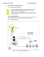
Page 54: ... Terminal Mounting Strip CAUTION Allow only an authorized dealer to install or service the your Sea Tel System components Unauthorized installation or service can be dangerous and may invalidate the warranty 3 9 2 Preparing BDE Location Prepare the Rack or other location for the ACU Terminal Mounting Strip and base multiplexer panel Prepare the mounting locations for the other Below Decks Equipmen...

Page 55: ...rated breaker or UPS 3 10 2 Connecting the BDE AC Power Cables Connect the AC power cables that supply power to the Below Decks Equipment ACU satellite modem phone fax computer and all other equipment to an outlet strip fed from a suitably rated breaker or UPS 3 10 3 Connecting the ADE IF Coaxes 1 Attach the TXIF coax from the antenna to a shorter section of coax to reach the TX Output of the Dipl...

Page 56: ...with FCC Order 04 286 and WRC 03 Resolution 902 There are several functional connections that may be made on the TMS connectors Although you may not need to make all of these connections they are listed here for clarification during the installation process Connect the 9 pin ribbon cable from this PCB to J2 NMEA DB9 on the rear panel of the ACU Connect the 25 pin ribbon cable from this PCB to J1 S...

Page 57: ...ut This hardware connection is also routed to the Console and OBM RJ45 ports JP5 Voltage Output Select Select 12VDC or 24VDC Default is 12VDC JP6 GPS NMEA Output Select Default is SHORTED Shorted provides GPS latitude longitude in alternating GGA GLL formatted messages to be outputted on the Terminal Mounting Strip NMEA output terminals This hardware connection is also routed to the Console and OB...

Page 58: ...GC readings below 2048 are considered a low condition and indicate modem lock and AGC readings above 2048 are considered a high condition and indicate modem unlock If you find the AGC reading for locked and unlocked conditions need to be reversed you must add 128 to your current SYSTEM TYPE parameter Turn tracking OFF when checking the external AGC inputs Be sure to properly retune the receiver fr...

Page 59: ...mp while the 126865 2 assembly supplies 5Vdc 2Amps GND Screw terminal is the ground reference for the regulated and unregulated power terminals 12 24 Screw terminal is commonly used to provide operating voltage to an external GPS Dual Antenna Arbitrator or other below decks tone generators or switches Voltage output is based on the T M S assemblies JP5 jumper settings 3 10 7 8 TS5 NMEA A B GPS out...

Page 60: ...r cable for the Antenna Pedestal and RF Equipment is routed into the AC Power Breaker box and connected to the breaker terminals Sea Tel recommends that separate dedicated AC Power be provided for the Marine Air Conditioner Do NOT combine with the AC Power provided for the Antenna Pedestal and RF Equipment This AC Power cable is routed into the Marine Air Conditioner and terminated to the AC termi...

Page 61: ...sure that Antenna power is ON and that the antenna has completed initialization At the ACU 1 From the ACU REMOTE BALANCE parameter Enable balance mode refer to your ACU manual The screen should now display REMOTE BALANCE ON At the Antenna 2 At the Antenna Balance the antenna with the elevation near horizon referred to as front to back balance by adding or subtracting small counter weights 3 Then b...

Page 62: ... under calm sea conditions and with DishScan Drive turned off as shown below The Cross Level displayed above the reference line indicates that the CL axis is being driven CCW Left in CL Example The antenna pictured in the screen capture below is imbalanced so that it is Right Heavy The CL trace is plotting above the red reference line indicating that CCW drive is required to keep the Cross Level b...

Page 63: ...The Azimuth display plots below the red line as the antenna is driven CW and plots above the red line as the antenna is driving CCW 3 16 Setup Refer to the Setup information in the next section of this manual and in the Setup section of your ACU Manual ...

Page 64: ...Installation 144 Radome 9711 44 Ku Band TXRX 3 40 This Page Intentionally Left Blank ...

Page 65: ...ts 2760 Permanent strength for up to 1 diameter fasteners 290 Wicking High strength for fasteners which are already assembled WARNING Hoisting with other than a webbed four part sling may result in catastrophic crushing of the radome Refer to the specifications and drawings for the fully assembled weight of your model Antenna Radome and assure that equipment used to lift hoist this system is rated...

Page 66: ...nd install the equipment Assure that you have a large flat level open area to sub assembly the baseframe pedestal dish feed and the upper lower sections of the radome This area should be clean and free of debris refer to the Installation chapters of Antenna and Antenna Control Unit manuals We recommend that you place the crates in the area that you have chosen to assembly each of these major compo...

Page 67: ...ottom section of the crate and lift the outer frame off 3 Remove the plastic covering Reflector shown in the raised position Base Frame Feed Assembly some systems have multiple feeds Waveguide some systems and the Feed Struts are hidden by the reflector in this picture See steps 4 6 below 4 Feed Struts wrapped and tied to the wooden diagonal 5 Feed Assembly and LNB Box Contains Feed Assembly LNB F...

Page 68: ... in the Pedestal Crate 4 3 3 Pedestal Crate We recommend that you place the Pedestal Crate in the area that you have chosen to assembly it 1 This is the Pedestal crate 2 Remove the outer frame top and sides of the crate by removing the Philips head screws placed around the bottom of that secure the outer frame to the bottom section of the crate and lift the outer frame off 3 Remove the plastic cov...

Page 69: ...scellaneous Box Stage these items in the location where the Pedestal will be assembled NOTE Some systems may have lager groups of assembled counterweight on the pallet 4 3 4 Radome Crate We recommend that you place the Radome Crate in the area that you have chosen to assemble the Radome onto the base frame 1 This is the Radome crate 2 Remove the screws nails around the crate walls to expose the co...

Page 70: ...Struts and Hardware Kit are located in this crate If there are two Feed LNB units they will each be in separate boxes Unpacking the Base Fame and Reflector 1 Open the crate to expose the contents as described above 2 Remove the lower lag bolts from the L brackets left and right that hold the reflector support structure legs to the crate Note There is one L bracket on each side Only remove the lowe...

Page 71: ...ut the straps that restrain the Base Frame Feet and Hardware Kit Box 9 Move these items to the area where the base frame will be assembled Note You will assemble the Base Frame later in the installation instructions 10 Cut the tie wraps that hold the Feed Struts Top Left and Right to the wooden diagonal 11 Keep the struts in this area as the feed will be installed on the reflector while it is stil...

Page 72: ...tuds in the scalar plate through the ends of the feed struts 21 Apply Loctite to the six studs install the flat lock washers and tighten the nuts onto each the studs to torque spec 22 If more than one drop in feed is provided with your system only un package the feed which will be first used after the ADE is completely assembled 23 Refer to feed installation procedures later in this chapter to ins...

Page 73: ... 5 Disconnect the coax connections to the LNB s 6 Disconnect the flexible waveguide from the rigid waveguide 7 Disconnect the feed harness 8 Tie the reflector down or have someone hold it until the drop in feeds have been swapped CAUTION The dish will be very back heavy when the drop in feed is removed therefore the reflector will rise VERY abruptly if not held down until the weight of the feed is...

Page 74: ...nt aligned to the center of strut 2 right strut as view from the front of the reflector Alignment mark scribed into the bottom end of the feed assembly 13 Apply Loctite 242 to install and tighten the eight screws see red arrows through the front of the scalar plate and into the end of the drop in feed assembly ...

Page 75: ...section from the rotary joint on the TX port of the feed to the top end of the rigid waveguide 15 Tie the harness coaxes to the waveguide rotary joint with a cable tie 16 Wrap the orange receive coax around the feed and connect it to the Cross Pol LNB hidden behind the feed in this view This wrap is required to allow the feed to rotate through its full 270 degree 135 range of rotation ...

Page 76: ...feed harness and connect it to the IDC connector This harness does not rotate with the feed during rotation 19 On the back side of the reflector route and connect the harness to the Feed DB25 port on the PCU as required 20 On the back side of the reflector route the Cross Pol LNB coax orange to the J1 NC connector of the coax switch on top of the PCU 21 On the back side of the reflector route the ...

Page 77: ... Stage these items in the location where the Pedestal will be assembled 3 Cut the band holding the Hardware to assemble Pedestal to Spider Assure that this hardware stays with the mounting spider 4 Cut the remaining restraints and remove the mounting spider Stage it with the location where the base frame will be assembled 5 Cut the bands holding the RF Box or boxes depending on product Stage these...

Page 78: ...ting straps 10 If large counter weight assemblies which have been removed from the equipment frame are packaged with the pedestal in this crate cut the bands or unbolt them from the pallet and stage them in the location where the Pedestal will be assembled 11 Remove the 4 bolts securing the wooden vertical supports from the Pedestal Arm Assemblies There will be 2 on the right and 2 on the left 12 ...

Page 79: ...Manual Installation chapter 3 Remove the straps that restrain the radome cap Leave the radome cap on the pallet with the radome panels for use during the radome assembly 4 Use diagonal cutters or shears to cut the bands that restrain the Hardware kit in the crate Leave the hardware kit on the pallet with the radome panels for use during the radome assembly 5 Use diagonal cutters or shears to cut t...

Page 80: ...nge order of these steps however in the end the objective is to have a well sealed radome with flanges that are clean of excess caulking In addition it is important that the ADE is structurally sound for severe weather conditions 4 7 2 Sub assemble the Base Frame Assembly Refer to the Base Frame Assembly drawing for your system and the procedure below NOTE Unless otherwise indicated all nuts and b...

Page 81: ...e pan pieces on the base frame Install the mounting hardware in the four pan mounting holes 5 Align the base pan perimeter holes to the mounting holes in the base frame Note You may want to temporarily insert bolts in 8 12 equidistant holes around the perimeter of the base pans to provide good alignment throughout the perimeter hole pattern 6 Apply Loctite to the mounting hardware and tighten If a...

Page 82: ...radome The riser panels and the lower half of the radome can be assembled on the baseframe You may choose to loosely assemble all of these panels then spread caulk the vertical seams and tighten that hardware Then install the pedestal assembly install the reflector assembly install the top sub assembly of the radome spread caulk and tighten the horizontal seams equator seam lower to riser and rise...

Page 83: ...tom left and right edges at each flange joint The tape will be removed just before the radome caulking has had time to set Messy smeared caulking will make the outside of the radome look bad 3 Open each vertical seam wide enough to install a good bead of silicone caulk apply loctite to and then firmly tighten all of the bolts in that seam Smaller beads of caulking can be applied from outside and i...

Page 84: ...octite to and then firmly tighten all of the horizontal flange bolts 12 Clean off the excess caulking from the inside and outside of the radome base where the riser panels are attached to the base 13 Remove the tape from the bottom edge of the outside of the riser panels 14 On a flat surface loosely assemble the 8 lower panels using the hardware provided Do NOT tighten the bolts at this time Assur...

Page 85: ...e removed just before the radome caulking has had time to set NOTE It is extremely important to assure that the flanges are properly aligned before the bolts are tightened and kept in alignment as the hardware is aligned This is necessary for the inside clearance and the outside aesthetic appearance of the radome Please note this picture shown good alignment as observed from inside the radome and ...

Page 86: ...4 22 Bad flange alignment 16 Open each seam wide enough to install a good bead of silicone caulk apply loctite to and then firmly tighten all of the bolts in that seam Smaller beads of caulking can be applied from outside and inside if you prefer ...

Page 87: ...bly to raise it up off of the ground 22 Attach 4 radome lifting brackets PN 131514 2 or other lifting arrangement to four opposite vertical flange mounting points every other vertical flange Orient the brackets with the shackle inside the perimeter of the bottom radome flange Hold the bracket under the bottom flange and install a bolt and fender washer down through the hole on one side of the vert...

Page 88: ...themselves will act a spacers to allow the caulking to be applied in the horizontal seam between these two sections of the radome 28 Install loosely hardware in all the holes around the perimeter of this horizontal flange except where the lifting brackets are installed Leave all of this hardware loose at this time 29 Start injecting caulking midway between two brackets 30 When close to the bracket...

Page 89: ... horizontal alignment of the panels Good alignment of the bottom edge of the upper panels is important for good seal between the upper and lower panels NOTE The person who is working inside installing hardware applying Loctite tightening hardware and cleaning the inner flanges will remain inside until the cap and lifting brackets are installed 37 To provide a clean caulked seam all around the pane...

Page 90: ...f the radome Please note this picture shown good alignment as observed from inside the radome and below a picture of poor flange alignment Good flange alignment Bad flange alignment 38 Open each seam wide enough to install a good bead of silicone caulk apply Loctite to and firmly tighten all of the bolts in that seam Smaller beads of caulking can be applied from outside and inside if you prefer 39...

Page 91: ...anel assembly have someone hand the cap to you and insert the cap into the top of the radome with a twisting rotation This will evenly spread the caulking and align the bolt holes inside the radome top Someone must be inside to align holes and insert the bolts 44 Install the radome cap using the provided hardware CAUTION Do NOT over tighten the hardware Only tighten until the fiberglass STARTS to ...

Page 92: ...e of the bracket and tighten a nut on the underside of the bracket 50 Install a second bolt and fender washer down through the hole on the other side of the vertical seam through the slot on that side of the bracket and tighten a nut on the underside of the bracket 51 Repeat steps 16 17 to install the other 3 brackets under opposing flanges every other vertical seam 52 Attach web strap lifting sli...

Page 93: ...e mounting bolts Note As an alternative the stand can be mounted to and lifted with the pedestal in step 22 below 2 Refer to drawing 135099 1 in the drawing section of the manual for installation of the Ku Band RF Equipment 3 Mount the Ku Band RF Equipment on the right side of the pedestal foreground of this view assuring that the waveguide port is facing the back of the Ku Band dish 4 Connect AC ...

Page 94: ...powering the equipment OFF 8 Install the pedestal mounting hardware Apply Loctite and tighten these bolts to torque spec 9 Stow the pedestal at zenith using the stow brace kit provided with the antenna system refer to the stow procedure in the maintenance chapter of this manual 10 Attach two small S hooks to two web lifting straps 11 Hook the two lifting strap S hooks into the end of the tubing of...

Page 95: ...the Installing the Co Pol Cross Pol feed section for routing of the coaxes 19 Connect the flexible waveguide section from the top end of the rigid waveguide to the Waveguide Rotary Joint on the TX port of the feed The antenna pedestal General Assembly is now completely assembled in the bottom half of the radome and is ready for you to put the top half of the radome on 4 7 6 Installing the Marine A...

Page 96: ...s 3 Loosely attach the upper panels to the lower panels using the hardware provided Do NOT tighten the bolts at this time NOTE It is extremely important to assure that the flanges are properly aligned before the bolts are tightened and kept in alignment as the hardware is aligned This is necessary for the inside clearance and the outside aesthetic appearance of the radome Please note this picture ...

Page 97: ...er panels off of the lower panels about 6 Install a good bead of caulking between the bottom of the upper panels and the top of the lower panels tighten all of the bolts in that seam smaller dual beads of caulking can be applied from outside and inside if you prefer Remove the wedges and radome lifting brackets and then firmly tighten all the bolts 7 Remove the tape from the upper and lower panels...

Page 98: ...odel Antenna Radome and assure that equipment used to lift hoist this system is rated accordingly CAUTION The antenna radome assembly is very light for its size and is subject to large swaying motions if hoisted under windy conditions Always ensure that tag lines attached to the radome base frame are attended while the antenna assembly is being hoisted to its assigned location aboard ship 1 Enter ...

Page 99: ...d crane or derrick 3 The radome assembly should be positioned with the BOW marker aligned as close as possible to the ship centerline Any variation from actual alignment can be compensated with the AZIMUTH TRIM adjustment in the ACU so precise alignment is not required 4 8 2 Install Antenna Radome Baseframe Bolt or weld the legs of the radome base frame directly to the ship s deck If the deck is u...

Page 100: ... 6 feet of the rear panel connections of the ACU It also is one rack unit height 3 Install the Base Multiplexer Panel on the rear of the 19 equipment rack or other suitable location that is within 6 feet of the rear panel connections of the ACU It is four rack unit height 4 Install the Line Amplifier Panel on the rear of the 19 equipment rack or other suitable location that is within 6 feet of the...

Page 101: ...el 4 10 4 Connect the Modem TXIF Coax Connect the TXIF coax from the Base Multiplexer Panel to the Satellite Modem TX Output 4 10 5 Antenna Control Unit Connections Figure 1 2 Rear Panel DAC 2202 ACU 4 10 5 1 Antenna Control Serial Cable Connect the antenna control serial cable from the Base Multiplexer to J4A on the DAC 2202 4 10 5 2 ACU to Terminal Mounting Strip Connections Connect the TMS to t...

Page 102: ...ontrol a band selection switch or tone generator Default is OPEN Shorted provides DC Voltage output determined by JP5 setting on the SW1 screw terminal to supply voltage to a tone generator or band select switch Open provides continuity output short to ground or open circuit on the SW1 screw terminal to control devices which have their own power source JP2 SW2 blockage RF radiation hazard output P...

Page 103: ... Test chapter for more information 4 10 7 3 J2 OBM Port The Out of Band Management port is used to connect the ACU to the out of band management device through the Terminal Mounting Strip This port is also a straight Serial RJ 45 port 4 10 7 4 TS1 Control Interface Connections AGC GND External AGC or Modem Lock input External AGC input to the DAC 2202 must be 0 to 15 Volts DC analog signal positiv...

Page 104: ...connecting a SW2 wire connection to the modem to comply with FCC Order 04 286 and WRC 03 Resolution 902 Dual or Quad Antenna Arbitrator coax switches in dual antenna configurations The coax switches select which antenna is feeding signal to the below decks equipment Mute the Transmit output of the Satellite Modem used in TX RX antenna configurations when the antenna is positioned where people may ...

Page 105: ... connections to assure that it is safe to energize the equipment 4 12 Power Up Verify that all shipping straps and restrains have been removed prior to energizing the antenna When all equipment has been installed turn ACU Power and Antenna power ON The ACU will initially sequentially display SEA TEL MASTER and DAC 2202 VER 6 xx followed by SEA TEL RCVR and SCPC VER 5 xx followed by SEA TEL IO MOD ...

Page 106: ...as described in the Setup section of this manual If initialization still fails this indicates a drive or sensor problem refer to the Troubleshooting section 4 15 2 Home Flag Position Note the approximate position of the antenna relative to the bow of the ship while it is at the home switch position This information will be used later to calibrate the relative position display of the antenna 4 15 3...

Page 107: ... weight during this step 5 When completed the antenna will stay at any position it is pointed in for at least 5 minutes with no ship motion 6 Do NOT cycle antenna power to re Initialize the antenna Return to the ACU which is still in REMOTE BALANCE mode and press ENTER to exit Remote Balance Mode When you exit Balance Mode the antenna will be re initialized which turns DishScan Azimuth Elevation a...

Page 108: ...when the antenna requires CW drive Up in elevation Example The antenna pictured in the screen capture below is imbalanced so that it is Front or Bottom Heavy The LV trace is plotting above the red line indicating that the LV axis is being driven CW to maintain the current elevation position The Azimuth display plots below the red line as the antenna is driven CW and plots above the red line as the...

Page 109: ...the EL TRIM selection Press BOTH the LEFT and the RIGHT arrow keys momentarily to access to the SAVE NEW PARAMETERS parameter Access is only required after installation or repairs of your antenna system These parameters should only be changed by an authorized service technician CAUTION Improper setting of these parameters will cause your system to not perform properly Also refer to the SETUP secti...

Page 110: ...TRACK DISP parameter This parameter value is for use with iDirect 5000 Series satellite modem to provide Modem Lock input Modem TX Mute functions Refer to Setup Modem Connect Setup and Test for values for some other common Satellite Modems and other SYSTEM TYPE parameter information REMOTE PARAMETER Ku Band Optimize using Lesson PCU Configuration Number N0xxx 215 Leave at factory Defaults Home Fla...

Page 111: ...destal The factory default selections and SW1 status for your antenna is listed in the following table TRACK DISP Setting Displayed band selection ADE Band Select Parameters Tone Voltage Aux Status TMS SW1 Status 0130 Xp B1 Xp B2 Xp B3 Xp B4 Cp B1 Cp B2 Cp B3 Cp B4 Tone OFF Volt 13 Aux 0 Tone ON Volt 13 Aux 0 Tone OFF Volt 18 Aux 0 Tone ON Volt 18 Aux 0 Tone OFF Volt 13 Aux 1 Tone ON Volt 13 Aux 1...

Page 112: ...Basic Setup of the ACU 9711 44 Ku Band TXRX 5 4 This Page Intentionally Left Blank ...

Page 113: ... 2 for Step By Step gyro or NMEA gyro 1 for 1 1 Synchro with S D Converter 0 for No Gyro linear AZ Search Mode No Heading input available 6 2 Updating the GYRO TYPE parameter To manually update press the LEFT arrow key to bring the cursor under the least significant character Continue to move the cursor until the desired character to be edited is underscored selected Use the UP or DOWN arrow keys ...

Page 114: ...Setup Ships Gyro Compass 9711 44 Ku Band TXRX 6 2 This Page Intentionally Left Blank ...

Page 115: ...enna pedestal The factory default selections and SW1 status for your antenna is listed in the following table TRACK DISP Setting Displayed band selection ADE Band Select Parameters Tone Voltage Aux Status TMS SW1 Status 0130 Xp B1 Xp B2 Xp B3 Xp B4 Cp B1 Cp B2 Cp B3 Cp B4 Tone OFF Volt 13 Aux 0 Tone ON Volt 13 Aux 0 Tone OFF Volt 18 Aux 0 Tone ON Volt 18 Aux 0 Tone OFF Volt 13 Aux 1 Tone ON Volt 1...

Page 116: ...Setup Band Select 9711 44 Ku Band TXRX 7 2 This Page Intentionally Left Blank ...

Page 117: ...apture from Lyngsat com 8 2 KHz The KHz rate entered into the ACU is an absolute value that is entered directly in this sub menu window This value may have been provided by your air time provider or have been calculated In the example above 1018 0 MHz was calculated 1018 MHz 000 KHz therefore the KHz entry would be 000 If the provided calculated value had been 1018 250 1018 would have been entered...

Page 118: ...n to control toggle the voltage output of the ADE 400MHz FSK modem For detailed information refer to the SETUP Band Select section of this document 8 6 SAT SKEW SKEW is used to optimize the polarization of the feed to the desired satellite signal In VSAT systems this is normally adjusted during the cross pol isolation testing with the Network or Satellite Provider refer to Optimizing Cross Pol Iso...

Page 119: ...ointing to the LEFT of the bow line If the antenna stops driving before the bow line when targeting a satellite it will fall short of the desired satellite by exactly the same number of degrees that it fell short of the bow line You must calibrate HFO using either of the methods below If the antenna is pointing to the RIGHT of the bow line If the antenna continues to drive past the bow line when t...

Page 120: ... Peak 227 0180 5 46 5 and difference is 46 5 degrees 7 I can calculate what the correct value for the Home position of the antenna by subtracting because home was to the left of bow this difference of 46 5 from the bow line position 360 0 Therefore home should be 313 5 Relative 8 I now calculate the HFO 313 5 360 x 255 0 87 x 255 222 06 which I round off to 222 9 I set and Save HFO to 222 using th...

Page 121: ...rrow keys to increment decrement the underscored value When you have finished editing the display value press ENTER to send the HFO value command to the PCU but it is not saved yet If you want to find out what the current HFO value is key in N6999 and hit ENTER When completed you must save the desired HFO value Press ENTER several times to select the REMOTE PARAMETERS display Press the LEFT or RIG...

Page 122: ...Setup Home Flag Offset 9711 44 Ku Band TXRX 9 4 This Page Intentionally Left Blank ...

Page 123: ...hout submitting the new AZ and EL Trim values NOTE AUTO TRIM LOCKED will be displayed on the front panel indicating that the AUTO TRIM Feature is NOT allowed if all of these conditions are not met The ACU must be actively tracking a satellite AGC above threshold and The ACU must have positive SAT ID internal NID match or external RX lock received from the Satellite Modem and The elevation angle of...

Page 124: ...ut reference Azimuth Trim does not affect REL azimuth reading Increase number to increase displayed value Refer to Optimizing Targeting in the Setup section of your antenna manual To update While in the AZ TRIM sub menu press the LEFT arrow key to bring the cursor under the ones digit Press the UP or DOWN arrow key to increment or decrement the selected digit Minus values are entered by decrementi...

Page 125: ...e this pattern by using the following settings SEARCH INC set to the default value for the frequency band that your antenna model is currently being used for typically 15 counts SEARCH LIMIT initially set to the default value After targeting has been optimized the search limit can be adjusted if desired SEARCH DELAY default or any number of seconds from 1 255 that you would prefer that the ACU wai...

Page 126: ...t MUST be OFF when the elevation angle is greater than 75 degrees It Must be ON if you are experiencing frequent or constant gyro read errors error code 0001 Target the desired satellite longitude value but include an odd tenths digit ie if you desire to target inclined satellite 186 0 W you would key in SAT 186 1 W for the ACU to do an inclined search The Antenna Control Unit calculates the Azimu...

Page 127: ...udes even tenths digit values ie SAT 101 0 W or SAT 101 2 W If the desired satellite longitude includes an odd tenths digit you must round it up or down one tenth to make the tenths digit EVEN The Antenna Control Unit calculates the Azimuth Elevation and Polarization values it will use to target the antenna However without heading input the ACU cannot target a true azimuth position relative to tru...

Page 128: ... character Use the LEFT or RIGHT arrow key to move the cursor left or right to select other characters to modify When you are finished modifying press ENTER to execute the new value OR press NEXT to abort and exit setup mode 11 2 2 EL STEP SIZE For proper DishScan operation this parameter must be set to factory default value of 0000 To manually update press the LEFT arrow key to bring the cursor u...

Page 129: ...en the signal level AGC drops below threshold Units are in seconds Range is 0 255 seconds Default setting is 30 seconds A setting of 0 disables the automatic search initiation To manually update press the LEFT arrow key to bring the cursor under the least significant character Continue to move the cursor until the desired character to be edited is underscored selected Use the UP or DOWN arrow keys...

Page 130: ...Setup Searching 9711 44 Ku Band TXRX 11 6 This Page Intentionally Left Blank ...

Page 131: ...kage between the two azimuth limit points in the EL LIMIT 34 parameter AZ LIMIT 5 is the Lower Relative AZ limit CCW point and AZ LIMIT 6 is the Upper Relative AZ limit CW point for pattern mapping of ZONE 3 Enter the elevation value that represents the top of the blockage between the two azimuth limit points in the EL LIMIT 56 parameter AZ LIMIT 7 is the Lower Relative AZ limit CCW point and AZ L...

Page 132: ...eeded repeat setting AZ LIMIT 3 4 for a second ZONE and then AZ LIMIT 5 6 if a third ZONE is needed All unneeded zone AZ LIMIT pairs must be set to 0000 Set the upper elevation limit of each blockage zone also entered in degrees multiplied by 10 EXAMPLE 1 Three blockage Zones A ship has a Sea Tel antenna mounted on the port side and an Inmarsat antenna mounted on the starboard side A mast forward ...

Page 133: ...tion is greater than 42 degrees the antenna will no longer be blocked ZONE 2 begins AZ LIMIT 3 at 254 degrees Relative and ends AZ LIMIT 4 at 278 degrees Relative Multiply these Relative positions by 10 Enter AZ LIMIT 3 value of 2540 and AZ LIMIT 4 value of 2780 In this case the Antenna B height only causes blockage up to an elevation of 12 degrees so we set EL LIMIT 34 to 0120 If the antenna is b...

Page 134: ...age up to an elevation of 70 degrees so we set EL LIMIT 34 to 0700 If the antenna is between these two AZ Limit points but the elevation is greater than 70 degrees the antenna will no longer be blocked ZONE 3 begins AZ LIMIT 5 at 155 degrees Relative and ends AZ LIMIT 6 at 205 degrees Relative Multiply these Relative positions by 10 Enter AZ LIMIT 5 value of 1550 and AZ LIMIT 6 value of 2050 In th...

Page 135: ...e DC voltage output on TS4 JP1 SW1 This output would be used for below decks Band Select to control a band selection switch or tone generator Default is OPEN Shorted provides DC Voltage output determined by JP5 setting on the SW1 screw terminal to supply voltage to a tone generator or band select switch Open provides continuity output short to ground or open circuit on the SW1 screw terminal to co...

Page 136: ...d to the Console and OBM RJ45 ports Open disconnects the GPS output from the Terminal Mounting Strip NMEA output terminals 13 2 iDirect Modems The 5100 mobile mode can be set to 1 Serial to use the Console port RJ 45 serial connector or 2 Ethernet to use a LAN connector for TX Mute Modem Lock and GPS position communication with the ACU Terminal Mounting Strip Jumpers JP1 Open JP2 Shorted JP3 Open ...

Page 137: ... Infinity 5100 Use an RJ 45 straight serial cable connected from the Terminal Mounting Strip Console Port connector to the Console Port connector on the rear panel of the modem 13 6 2 Comtech Modems Connect the 126877 harness assembly from the 15 pin serial port on the 570L or 600L modem to the Terminal Mounting Strip screw terminals 1 Cut the resistor Yellow wire off of the pin on the White wire ...

Page 138: ...urrent sink of 0 5 amps max to control below decks dual antenna coax switches or TX Mute control to a satellite modem for radiation hazard control or TX mute requirements for FCC compliance Relative Azimuth value is normally only visible in the Antenna main menu display The Azimuth entry menu normally displays Azimuth position DishScan tracking signal and AGC When Search limit is reached the anten...

Page 139: ...h a current sinking capability of 0 5 Amp This logic output control signal is used for When used as simple BLOCKED logic output for a single Sea Tel antenna this output could be used to light a remote LED and or sound a buzzer to alert someone that the antenna is blocked and signal is lost In a Dual Antenna installation this logic output s is used to control Dual Antenna Arbitrator panel of coax s...

Page 140: ... Turn tracking OFF so that the antenna stays pointed ON satellite 3 Press NEXT until the Satellite menu is displayed Press ENTER 3 times to display the Frequency entry window Record the frequency that the tracking receiver is currently tuned to Press LEFT or RIGHT arrow key to bring up the cursor under the units digit Use the UP or DOWN arrow keys to increment or decrement the selected digit use t...

Page 141: ...will still be effective but will be lost when power is removed or the RESET key is pressed Simultaneously press and quickly release the LEFT and RIGHT arrow keys to access SAVE NEW PARAMETERS directly from any other menu display Verify that the change s you have made is are correct and then select SAVE NEW PARAMETERS Press UP arrow and then ENTER to save any recent changes into the ACUs NVRAM for ...

Page 142: ...Setup Modem Connections Setup and Test 9711 44 Ku Band TXRX 13 8 This Page Intentionally Left Blank ...

Page 143: ...l isolation with the airtime provider network operation center or satellite provider 14 2 Optimizing Auto Polarization on Receive Signal This procedure optimizes the linear polarization of the feed based on the received signal level 1 Verify that tracking is ON and that the antenna is peaked on your targeted satellite targeting calculates the azimuth elevation and polarization angles 2 Go to the S...

Page 144: ...e press the UP arrow to increment or the DOWN arrow to decrement the value and then hit the ENTER key to adjust the feed 6 The technician should indicate whether the adjustment you made improved or worsened the cross pol isolation If it improved he will have you make another small adjustment in the same direction If it worsened he will have you make a small adjustment in the opposite direction 7 P...

Page 145: ...DacRemP diagnostic software that your dealer will use when necessary 15 4 REMOTE MONITOR This parameter was used to monitor the results of a diagnostic command which was sent to the PCU 15 5 To Disable Enable DishScan When running a beam pattern test a programmed sweep for NOC Satellite Operator balancing the antenna or motor diagnostics where you want the drives AZ EL CL not to be oscillating you...

Page 146: ...bias Satellite Reference Mode can be used as a diagnostic mode to determine if tracking errors are caused by faulty gyro inputs I t is normally OFF as long as you have good gyro compass input It MUST be OFF when the elevation angle is greater than 75 degrees Satellite Reference Mode MUST be ON when No Gyro Compass is available Frequent or constant ACU Error Code 0001 Gyro Compass has failed To vie...

Page 147: ...ion no one should be allowed anywhere within the radiated beam being emitted from the reflector The ultimate responsibility for safety rests with the facility operator and the individuals who work on the system 16 1 System Power up Turn the Power switch on the louvered panel of the antenna pedestal ON This will energize the antenna pedestal and the associated RF equipment Turn the Antenna Control ...

Page 148: ... Tracking ON OFF and choose the desired Band Selection from the list generated from the TDISP parameter setting 16 5 Manually Targeting A Different Satellite If you are not using OpenAMIP to control the ACU or some other method of remotely accessing the ACU the operator will have to manually change settings and parameters in the ACU to target a different satellite than you have been previously bee...

Page 149: ...a Menu AZ 123 4 EL 056 7 REL 234 5 AGC 1234 Status SEA TEL INC REMOTE 9711 VER 2 03 Brings up the cursor CONTROL TRACKING On Lin P Toggle through the list of possible BAND selections Brings up the cursor Toggle Reflector selection Assure that Reflector A for C Band is selected SAT 101 W THRS 1234 MHZ 1100 NID 1234 MHZ 1100 AGC 1234 KHz 250 AGC 1234 Satellite Menu Set to the desired MHz frequency t...

Page 150: ...Antenna Specific Operation 9711 44 Ku Band TXRX 16 4 This Page Intentionally Left Blank ...

Page 151: ...te the Latitude entry menu 3 Press the LEFT arrow key to display a cursor under the numeric value 4 Press the UP arrow key to increment the displayed value 5 Press the ENTER key to submit change 6 If automatic updating is working properly the Longitude value display will return to the current ships Longitude position within a few seconds 17 3 Heading Following Verify that the heading display in th...

Page 152: ...displayed AGC drops 100 counts approx 2 3 dB Do not drive antenna so far that AGC falls below threshold 6 Press the TRACK key to re enable tracking 7 Monitor the Azimuth and AGC Values for the next 20 30 seconds 8 Verify the Azimuth and AGC return to the values noted in step 4 9 Verify the amount of time it took for tracking to bring AGC back to peak is within the specifications Nominal time to ge...

Page 153: ... within 0 2 degrees The default output is contact closure to ground when the antenna is mis pointed therefore provides a ground to Mute the satellite modem on the SW2 terminal of the Terminal Mounting Strip If your satellite modem requires an open to Mute refer to SYSTEM TYPE parameter 16 value to reverse the output logic from the ACU To Test the blockage function 1 Press the NEXT key until you ar...

Page 154: ...Functional Testing 9711 44 Ku Band TXRX 17 4 This Page Intentionally Left Blank ...

Page 155: ...uals who work on the system 18 1 Troubleshooting the ACU The following paragraphs list the problems you might encounter when performing the functional checkout steps in the previous section of this manual Following the problems are suggestions of where to start looking to solve the problem Refer to the Drawings section of this manual and your antenna manual for any all pertinent block diagrams sch...

Page 156: ...on even if it does not display the correct heading go to step 2 If it moves in the correct direction but does not display the correct heading go to step 3 The gyro compass connects to the R1 R2 S1 S2 and S3 terminals CAUTION Electrical Shock Potentials exist on the Gyro Compass output lines Assure that the Gyro Compass output is turned OFF when handling and connecting wiring to the Terminal Mounti...

Page 157: ... not then a fuse is blown at the gyro repeater or there is an open between the repeater and the ACU Read between S1 and S2 S2 and S3 and finally S3 and S1 They should all read between 0 and 90 VAC The voltage level will change as the ship turns If one reading is very close to 0 volts wait until the ship has made a major change in heading and then check voltage again If the reading is still very lo...

Page 158: ...Installation Troubleshooting 9711 44 Ku Band TXRX 18 4 This Page Intentionally Left Blank ...

Page 159: ...ty for safety rests with the facility operator and the individuals who work on the system WARNING RF Radiation Hazard When the transmit receive system is in operation no one should be allowed anywhere within the radiated beam being emitted from the reflector The ultimate responsibility for safety rests with the facility operator and the individuals who work on the system 19 1 Warranty Information ...

Page 160: ...or side to side The antenna system is not pendulous so balanced is defined as the antenna remaining at rest when left in any position The REMOTE BALANCE parameter located at the end of the Remote Parameters after REMOTE TILT of the ACU When enabled Remote Balance Mode temporarily turns DishScan Azimuth Elevation and Cross Level drive OFF This function is required when trying to balance antenna sys...

Page 161: ...h motor for diagnostic purposes and verifying antenna balance By observing each trace the required drive of the antenna via the motor driver PCB may be established To view the Torque Commands select the graph chart This chart displays the Torque Command errors for each axis via three traces CL Cross Level LV Elevation and AZ Azimuth at a fixed 0 195 amps vertical division In all axes tracing cente...

Page 162: ...levation position The Azimuth display plots below the red line when the antenna is driven CW and plots above the red line as the antenna is driving CCW 19 3 3 To Reset Reinitialize the Antenna Select the REMOTE COMMAND window on the ACU and 1 Key in 94 and then hit the ENTER key note the decimal point to access the utility commands 0000 should appear in the command window 2 Key in 90 and then hit ...

Page 163: ...ings are required except when it is required to re configure a modem to operate in a different mode of operation i e converting a spares kit below decks modem to operate as an above decks modem or reconfiguring an ADE modem for M C integration with a newly installed RF package change that requires RS485 communications instead of RS422 Refer to the table below for the proper jumper settings Assembl...

Page 164: ...ve for the appropriate dash configuration for your modem assembly A flashing Red LED indicates no communication between modems 2 failed channels An LED alternating Red and Green indicates a single channel failure Solid green indicate dual channel communications lock between modems i e there is enough signal being received to establish communications Below Decks Modem Assembly Above Decks Modem Loc...

Page 165: ...e pedestal modem then converts the RF signal back to RS 232 422 485 before routing to the M C port of the above decks radio equipment via an interface cable 19 6 3 Channel Identification There are four base frequencies used in the 400MHz FSK modem assemblies The BDE Modem Transmits Pedestal M C at 452 5 MHz The BDE Modem Transmits Radio M C at 447 5 MHz The ADE Modem Transmits Pedestal M C at 465 ...

Page 166: ...cr BDE Modem Software Version and Configuration Query Modem Ver 1 00B 1 Software version configuration Dash 0000 cr ADE Modem RSSI Receive Signal Strength Indicator RSSI P 43 R 50 P Pedestal Control Channel R Radio Control Channel 1234 cr ADE Modem Serial Number Query Sn 00000102FC18 0273 cr ADE Modem Temperature Query Temp 27 5c Temperature expressed in Celsius 0411 cr ADE Modem Software Version ...

Page 167: ... 7 2 2 Using the Internal HTML Page 1 Logon to the ACU s Internal HTML page 2 Browse to the Communication Port Settings page 3 In the Command Window Type in the desired Modem Query and hit Send 4 Observe and or Record the displayed response 5 Repeat as required until all desired modem queries are noted 19 7 2 3 Using DacRemP 1 Open up DacRemP and select the Comm Diagnostics Tool cntrl c 2 In the R...

Page 168: ...olating a 400 MHz Modem Fault Procedure 1 Issue 0000 and 0000 queries to the ADE and BDE modems and record the responses ADE 0000 ______________ BDE 0000 ______________ 2 Compare your recorded responses to the list below to determine what modem fault s if any is present 3 Use the appropriate text following the failure table for a list of possible failures attributed to the failure type established...

Page 169: ...t RF M C P 65 R 65 P 65 R 65 BDE Transmit Or ADE Receive RF M C 19 7 3 1 1 NONE No failure communication failures between ADE and BDE modems 19 7 3 1 2 Receive IF Path The Following possibly points of failures assumes LED illumination on both modems Modem Configuration Verify BDE modem and ADE modem are properly configured jumper block settings Coax Cable failure Verify continuity on the below coa...

Page 170: ...acon is present the fault is the BDE modem 2 If 465 0MHz Transmit Beacon is NOT present fault is with the ADE modem 19 7 3 1 5 ADE No Response 2 ADE Modem Configuration Verify the ADE modem is properly configured jumper block settings Coax Cable failure Verify continuity on the items listed below repair or replace as required o Base Modem to connector bracket Base Rack Panel Assembly o CFE BDE to ...

Page 171: ...ent the fault is with the ADE modem 19 7 3 1 9 BDE Transmit Or ADE Receive Radio M C BDE Modem Tx Port Failure Not transmitting at 447 5MHz or ADE Modem Rx Port Failure Not receiving at 447 5MHz o Install Spectrum Analyzer in line with the Rx IF coax path 1 If 465 0MHz Transmit Beacon in present the fault is the BDE modem 2 If 465 0MHz Transmit Beacon is NOT present the fault is with the ADE modem...

Page 172: ... The dish will be very back heavy when the drop in feed is removed therefore the reflector will rise VERY abruptly if not held down until the weight of the feed is replaced 9 Remove the eight screws see red arrows from the front of the scalar plate to disconnect the drop in feed from the scalar plate 10 Remove the drop in feed assembly that is being replaced 11 Your scalar plate remains attached t...

Page 173: ...igned to the center of strut 2 right strut as view from the front of the reflector Alignment mark scribed into the bottom end of the feed assembly 13 Apply Loctite 242 to install and tighten the eight screws see red arrows through the front of the scalar plate and into the end of the drop in feed assembly ...

Page 174: ...n from the rotary joint on the TX port of the feed to the top end of the rigid waveguide 15 Tie the harness coaxes to the waveguide rotary joint with a cable tie 16 Wrap the orange receive coax around the feed and connect it to the Cross Pol LNB hidden behind the feed in this view This wrap is required to allow the feed to rotate through its full 270 degree 135 range of rotation ...

Page 175: ...arness and connect it to the IDC connector This harness does not rotate with the feed during rotation 19 On the back side of the reflector route and connect the harness to the Feed DB25 port on the PCU as required 20 On the back side of the reflector route the Cross Pol LNB coax orange to the J1 NC connector of the coax switch on top of the PCU 21 On the back side of the reflector route the Co Pol...

Page 176: ...t the Ku Band drop in feed assembly is installed with the alignment mark aligned with strut 2 the right side strut Alignment mark scribed into the end of the feed assembly 2 Assure that the DAC 2202 TX Polarity is set to 2 Horizontal TX 3 Set the DAC 2202 POL TYPE to 0009 4 Set Balance Mode ON 5 At the antenna loosen the top hidden by wires in this picture motor mounting screw 6 Loosen the bottom ...

Page 177: ...ne with the drop in feed alignment mark 9 While hold the OMT in alignment rotate the body of the motor CW to couple the drive and driven gears And tighten both motor mounting screws 10 Connect a volt meter to the pot wires Positive lead to IDC 4 pin 2 Gray wire Negative lead to IDC 4 pin 1 Brown wire ...

Page 178: ...ltage reading is 2 993 VDV 1 3 023 2 963 VDC 12 Carefully rotate the body of the pot CW to couple the drive driven gears while maintaining the specified voltage 13 Hold the pot in place and tighten the two mounting screws 14 At the DAC 2202 15 Verify that the Pol display in the Antenna menu reads 130 2 16 Set the DAC 2202 POL TYPE to 0072 17 Set Balance Mode to OFF 18 Resume normal operation ...

Page 179: ...e for you model antenna 19 9 1 To configure the PCU 1 Select the REMOTE COMMAND window on the ACU 2 Refer to the table below to key in the appropriate value for you model antenna to enter in the next step EXAMPLE For a 9497B L S or MK2 Model Antenna is system type 0209 3 Using the LEFT RIGHT and UP DOWN arrow keys set the Remote Command value to N0209 and press ENTER The display should now show N0...

Page 180: ...Maintenance 9711 44 Ku Band TXRX 19 22 This Page Intentionally Left Blank ...

Page 181: ...hanism during underway conditions when power is removed from the antenna assembly The normal operating condition for the Sea Tel Antenna system is to remain powered up at all times This ensures that the antenna remains actively stabilized to prevent physical damage to the antenna pedestal and reduce condensation and moisture in the radome to prevent corrosion If for some reason the antenna must be...

Page 182: ...aps As the straps are tightened observe the vertical isolation canister assembly as shown in Figure 4 6 Tighten straps until the canister has been pulled down approx to inch Do not over tighten You must leave approximately 1 8 inch clearance between the rubber stops and the azimuth driven sprocket to allow the vertical vibration isolation to function properly NOTE Remove both the straps and the bo...

Page 183: ...ating system 21 2 Installing the ADE Bluetooth Hardware The IOGear serial Bluetooth is shown below other manufacturer models may be used 1 Turn Tracking OFF at the ACU 2 At the ADE open the hatch in the base of the radome 3 Reach into the radome hatch to secure the AC power at the breaker 4 Rotate the antenna pedestal to access the PCU 5 Carefully enter into the radome hatch far enough to reach th...

Page 184: ...M port for your Bluetooth device 6 Once COM port is selected open a compatible Sea Tel diagnostic program ProgTerm or DacRemP 7 In the Sea Tel diagnostic program select the appropriate COM port for the Bluetooth refer to help in ProgTerm or DacRemP as appropriate 8 You are now ready to communicate wirelessly to your Sea Tel antenna system 21 4 Diagnostic Mode If you are doing diagnostics and will ...

Page 185: ...MK2 PCU Service Port If the devices retaining screws were secured unscrew them to remove the device from the PCU 7 Carefully exit the radome hatch 8 Reach into the radome hatch to turn AC power ON at the breaker 9 Allow the antenna to reinitialize 10 Secure the radome hatch 11 Retarget the satellite if desired 12 Return to normal operation 21 6 Removing the BDE Bluetooth Hardware 1 At the computer...

Page 186: ...e Installing the ADE Bluetooth Hardware and Installing the BDE Bluetooth Hardware paragraphs above 2 From the computer open ProgTerm 3 It is strongly recommended that you save a parameter dump of the ACU and PCU parameters 4 Use ProgTerm to update ACU or MK2 PCU software as you normally would 5 Verify that all of the system parameters are correct after the software upload 6 Retarget desired satell...

Page 187: ...tacked W Encoder Level Motor Size 34 Brushless DC Servo W Brake Cross Level Motor Size 34 Brushless DC Servo W Brake Inertial Reference 3 Solid State Rate Sensors Gravity Reference 2 MEMS Tilt Sensors AZ transducer 256 line optical encoder home switch Pedestal Range of Motion Elevation Joint Angle 15 to 100 degrees Cross Level Inclined 30 25 degrees Azimuth Unlimited Elevation Pointing 0 to 85 deg...

Page 188: ... 7 dBi at 6 18 GHz 48 45 dBi at 14 25 GHz RX Gain 38 5 dBi at 3 95 GHz 47 75 dBi at 11 85 GHz G T 30 elevation clear sky 28 2 dB k calculated FCC Input Power Spectral Density Limitation 14 0 dBW 4 KHz Minimum EIRP TVRO NA KU band Feed Type Prime focus with diplexer Xpol copol Port to Port Isolation Xpol 120 dB Port to Port Isolation copol 90 dB Cross Pol Isolation 35 dB typical 30dB within 1dB con...

Page 189: ... 12 25 12 75 GHz Local Oscillator Frequency 11 30 GHz Output IF Frequency 950 to 1450MHz Band 4 Voltage Required 18VDC 22 KHz Tone Input RF Frequency 10 70 11 70 GHz Local Oscillator Frequency 9 75 GHz Output IF Frequency 950 to 1950 MHz KU band TX Radio Package SSPB Comtech 125W PSAT 100W P1 dB Output Flange WR 75 Input Connector N type female RF Input Frequency Range 950 to 1700 MHz RF Output Fr...

Page 190: ...edestal Control Unit PCU Connectors AC Power 100 240 VAC 2A 1A USB Mini USB GPS Input RJ 11 Motor Control DA 15S Rotary Joint SMA RF M C DE 9S Feed DB 25S Service DE 9S Coax Switch LNB A J2 NO Co Pol SMA J3 COM Common SMA LNB B J1 NC Cross Pol SMA L Band SMA L Band Input Controls Configurable from GUI M C Interface 9600 Baud 400MHz FSK Status LEDs PCU Status Diagnostic Status of the PCU Modem Stat...

Page 191: ... weight MAX xxx kg 1800 LBS including Antenna Pedestal Assembly RF attenuation 1 5 dB 6 GHz dry 1 5 dB 12 GHz dry 1 5 dB 14 GHz dry Wind Withstand relative average winds up to 201 Kmph 125 mph from any direction Ingress Protection Rating IP 56 Radome Assembly 168 inch Type Frequency Tuned Material Composite foam laminate Size Diameter 426 72cm 168 inch Height 420 88cm 165 7 inch Hatch Size 45 72cm...

Page 192: ...nt or are treated to endure effects of salt air and salt spray The equipment is specifically designed and manufactured for marine use Chemically Active Substances Environmental Condition Test Level Sea Salt 5 percent solution 22 2 Below Decks Equipment Digital Control Unit DAC 2202 Standard 19 Inch Rack mount One Unit High Physical Dimensions 17 X 14 X 1 75 Inches 43 18 x 35 56 x 4 45 cm Input Vol...

Page 193: ... W NMEA string examples RX GPGLL 3800 4300 N 12202 6407 W 231110 A 32 GPGGA 231110 3800 4300 N 12202 6407 W 2 08 1 2 40 0 M 31 3 M 4A TX GPRMC 231325 A 3800 4300 N 12202 6405 W 000 0 184 9 190412 014 1 E 67 GPVTG 184 9 T 170 8 M 000 0 N 0000 0 K 74 L Band SCPC Tracking Receiver Tuning Range 950 to 2150 MHz in 1 KHz increments Input RF Level 85 to 25 dBm typical Output RF Level Input level 1dB typi...

Page 194: ... BDE NA Power Requirements DAC BDE 85 264 VAC 47 63Hz single phase 160 Watts max BDE Environmental Conditions Temperature 0 to 40 degrees C Humidity Up to 100 40 degrees C Non Condensing 22 3 Regulatory Compliance Survival Shock and Vibration IEC 60945 MIL STD 167 Operational Shock and Vibration Operational IEC 60945 Survival MIL STD 167 EMI EMC Compliance Ku Band ETSI EN 301 843 1 V1 4 1 2004 06 ...

Page 195: ...to 150 ft RG 213 RG214 or LMR 400 14 AWG up to 200 ft LDF4 50 Heliax or LMR 500 10 AWG Up to 300 ft LMR 600 6 AWG For runs longer that 300 feet Sea Tel recommends Single mode Fiber Optic Cables with Fiber Optic converters 22 4 3 Multi conductor Cables Customer Furnished Due to the voltage losses across the multi conductor cables Sea Tel recommends the following wire gauge for the AC DC multi condu...

Page 196: ... Band TXRX 22 10 22 4 6 Gyro Compass Interface Cable Customer Furnished Type Multi conductor Shielded Number of wires 4 Conductors for Step By Step Gyro 5 Conductors for Synchro Wire Gauge see Multi conductor Cables spec above Insulation 600 VAC ...

Page 197: ...S2 23 17 140167 1_B Balance Weight Kit EL CL 23 19 134867 1_F1 Antenna Assembly 2 4M Offset 23 21 140103 1_B TX Wavegiude run 23 23 136648 1_C Tx Rx Feed Sub Assembly Ku Band Linear DishScan 23 25 111365 17_S Radome Ass y 144 Inch 23 28 123723 9_E1 Radome Base Ass y 75 In STL 23 31 123908_B6 Installation Arrangement 23 34 122508_G A C Install Assy 75 Base 23 36 123496_C1 Air Conditioner Internal 2...

Page 198: ...Drawings 9711 44 Ku Band TXRX 23 2 This Page Intentionally Left Blank ...

Page 199: ...Y W DIPLEXER KU BAND 2 4 M ANTENNA E 11 1 129337 1 EA INSTALL KIT AIR CON BREAKER A 12 1 123496 2 EA AIR CONDITIONER R417A 220V DUAL 50 60HZ INTNL C1 15 1 125411 3 EA DAC 2202 SCPC RCVR 9 WIRE IF V 16 1 129615 1 EA BELOW DECK KIT L BAND 400MHZ RS 232 C 17 1 135098 8 EA CUSTOMER DOC PACKET 9711 44 A 26 1 122539 1 EA SHIP STOWAGE KIT XX97 B 27 1 114569 EA BALANCE WEIGHT KIT F 28 1 124877 1 EA DECAL ...

Page 200: ...EXER KU BAND 2 4 M ANTENNA E 11 1 129337 1 EA INSTALL KIT AIR CON BREAKER A 12 1 123496 2 EA AIR CONDITIONER R417A 220V DUAL 50 60HZ INTNL C1 15 1 125411 3 EA DAC 2202 SCPC RCVR 9 WIRE IF V 16 1 129615 1 EA BELOW DECK KIT L BAND 400MHZ RS 232 C 17 1 135098 8 EA CUSTOMER DOC PACKET 9711 44 A 26 1 122539 1 EA SHIP STOWAGE KIT XX97 B 27 1 114569 EA BALANCE WEIGHT KIT F 28 1 124877 1 EA DECAL KIT XX97...

Page 201: ...S Y 11 11 13 12326 A1 REFERENCE DRAWINGS 140163 SYSTEM BLOCK DIAGRAM 140162 ANTENNA SYSTEM SCHEMATIC 133746 PEDESTAL SCHEMATIC 123908 INSTALLATION ARRANGEMENT 121910 SHIPYARD SPEC 124877 DECAL KIT LIN 125W COMTECH QUAD 604 AC TXFMR 168 DOME 606 AC TXFMR QUAD COMTECH 125W LIN KU KU DASH BAND POL WATT RF MFR LNB OTHER SYSTEM WEIGHTS 2 DASH GA RADOME BASE FRAME AC KIT SYSTEM TOTAL 604 602 550 176 N A...

Page 202: ...TOR DRIVER X 31 2 EA 130082 56 A HARNESS EL CL MOTOR INTERFACE 56 IN 32 1 EA 130083 64 A HARNESS ASS Y AZ MOTOR INTERFACE 64 33 1 EA 130084 64 C HARNESS HOME FLAG ADAPTER 64 IN 34 1 EA 139646 84 A CABLE ASS Y 9711 PED AC PWR TO H BRI 35 1 EA 131493 3 A2 HARNESS ASS Y REFLECTOR G2 XX97 1 36 1 EA 138932 96 A CABLE ASS Y ETHERNET M C TO COMTECH 40 1 EA 139981 1 X2 CIRCUIT BREAKER BOX ASS Y 97IMA 20AM...

Page 203: ... WAVEGUIDE WR 75 180 DEG E BEND 77 1 EA 115477 6 C WAVEGUIDE WR 75 ROTARY JOINT L STY 78 1 EA 115551 313 E4 WAVEGUIDE WR 75 EXTENSION 1 3 IN 79 1 EA 125157 1 B DIPLEXER DPX75K C02 A WR 75 80 1 EA 128290 1 A1 WAVEGUIDE WR 75 180 DEG H BEND W BR 81 1 EA 140078 1 A FILTER REJECT METRIC KU BAND TRANS 100 1 EA 129615 1 C BELOW DECK KIT L BAND 400MHZ RS 23 101 1 EA 125411 3 T DAC 2202 SCPC RCVR 9 WIRE I...

Page 204: ...003 18 D ADAPTER BNC F F M 130 1 EA 116298 1 H INTERFACE HARNESS ASS Y SINGLE MODEM 131 1 EA 120643 10 C CABLE ASS Y RS232 9 WIRE STRAIGHT 132 1 EA 119479 10 C CABLE ASS Y CAT5 JUMPER 10 FT 133 1 EA 119478 5 E CABLE ASS Y RJ 45 SERIAL 60 IN 133 1 EA 126877 C4 HARNESS ASS Y COMTECH MODEM INTERFAC 3 SHT 3 OF SYSTEM BLOCK DIAGRAM 9711 44 PROD FAMILY LIT EFF DATE 11 22 2013 DRAWING NUMBER 140163 1 REV...

Page 205: ......

Page 206: ...ASS Y 9711 44 LPOD 4 1 EA 134867 1 F1 ANTENNA ASS Y 2 4M OFFSET 9711 5 1 EA 140103 1 B WAVEGUIDE RUN ASS Y 97IMA 44 PS2 L 6 1 EA 140167 1 B BALANCE WEIGHT KIT 9711 44 LPOD PS 11 1 EA 123530 5 E GROUND BONDING KIT DUAL RF 12 1 EA 121655 1 L LABELS INSTALLATION XX97 9711 STXX 14 1 EA 134420 1 A MK2 GPS KIT 1 SHT 1 OF GENERAL ASS Y 9711 44 PS2 LPOD PROD FAMILY 97 TX RX EFF DATE 11 22 2013 DRAWING NUM...

Page 207: ... X1 10 18 13 12096 A K D H ITEM 2 WAS 139982 1 ADD SHEETS 2 3 11 11 13 12326 B REFERENCE DRAWINGS 140162 ANTENNA SYSTEM SCHEMATIC 140163 SYSTEM BLOCK DIAGRAM 133746 PEDESTAL SCHEMATIC 5 3 12 4 1 14 8 2 1 15 WEIGHT JWM D C B A A B C D 1 2 3 4 5 6 7 8 8 7 6 5 4 3 1 OF 3 2 1 PROJECTION FINISH MATERIAL DRAWN BY APPROVED BY TITLE FIRST USED SIZE SCALE SHEET NUMBER REV B K D H 9 25 13 BY 140165 DRAWING ...

Page 208: ...D C B A A B C D 1 2 3 4 5 6 7 8 8 7 6 5 4 3 2 1 SIZE SCALE SHEET NUMBER DRAWING NUMBER REV B 1 15 140165 B 2 OF 3 ...

Page 209: ...D C B A A B C D 1 2 3 4 5 6 7 8 8 7 6 5 4 3 2 1 SIZE SCALE SHEET NUMBER DRAWING NUMBER REV B 1 15 140165 B 3 OF 3 ...

Page 210: ......

Page 211: ... CABLE TIE HOLDER 281 DIA PUSH MOUNT 50 2 EA 114593 148 SCREW SOCKET HD 8 32 x 3 4 S S 60 1 EA 114593 164 SCREW SOCKET HD 10 32 x 1 2 S S 66 1 EA 119952 011 A1 WASHER STAR INTERNAL TOOTH 10 S 68 1 EA 114580 011 WASHER FLAT 10 S S 70 4 EA 114586 537 SCREW HEX HD 1 4 20 x 3 4 S S 71 2 EA 114586 543 SCREW HEX HD 1 4 20 x 2 S S 72 2 EA 114586 545 SCREW HEX HD 1 4 20 x 2 1 2 S S 76 12 EA 114581 029 WAS...

Page 212: ...PER SEATEL SPEC 122930 APP G ATTACH TO ASS Y 7 WHERE SHOWN K D H DASH 1 2 ITEM 70 WAS 114586 535 DASH 2 ADD ITEM 3 12 8 11 9075 B K D H DASH 1 ONLY CORRECTED BOM ERROR ITEM 70 FROM ECO 9075 3 12 12 N A B1 K D H ADD ITEM 5 NOTE 5ERROR ITEM 70 FROM ECO 9075 4 10 12 9572 C K D H ADD NOTES 6 7 5 31 12 N A C1 K D H ADD 3 5 23 13 10662 C2 135099 D C B A A B C D 1 2 3 4 5 6 7 8 8 7 6 5 4 3 2 1 SURFACE RO...

Page 213: ...4586 623 B SCREW HEX HD 3 8 16 x 1 S S 55 6 EA 114580 032 WASHER FLAT 3 8 S S 1 OD X 13 32 56 6 EA 114580 038 C WASHER FLAT 3 8 S S 7 8 OD X 13 57 6 EA 114581 031 WASHER LOCK 3 8 S S 58 12 EA 114580 031 C WASHER FLAT 3 8 S S 59 12 EA 114583 031 NUT HEX 3 8 16 S S 1 SHT 1 OF RF MOUNTING SUB ASS Y LS COMTECH LPOD PS2 PROD FAMILY COMMON EFF DATE 11 22 2013 DRAWING NUMBER 136019 5 REV B2 ...

Page 214: ...OLES POSITION 01 04 12 10165 B1 K D H ADD 5 6 11 8 13 12326 B2 K D H N A D C B A A B C D 1 2 3 4 5 6 7 8 8 7 6 5 4 3 2 22 8 LBS 1 PROJECTION FINISH MATERIAL DRAWN BY APPROVED BY TITLE FIRST USED SIZE SCALE SHEET NUMBER DRAWING NUMBER REV APPROVED DATE 9797B 88 1 8 B B2 11 15 11 136019 1 OF 1 DRAWN DATE JWM RF MOUNTING SUB ASS Y REVISION HISTORY REV ECO DATE DESCRIPTION Tel 925 798 7979 Fax 925 798...

Page 215: ... 2 1 LBS 7 1 EA 108894 2 G1 WEIGHT TRIM 3 8 X 3 X 10 3 19 LBS 50 2 EA 114586 544 SCREW HEX HD 1 4 20 x 2 1 4 S S 51 2 EA 114586 548 SCREW HEX HD 1 4 20 x 3 1 4 S S 52 2 EA 114586 552 SCREW HEX HD 1 4 20 x 4 1 2 S S 58 12 EA 114580 029 WASHER FLAT 1 4 S S 59 6 EA 114583 029 NUT HEX 1 4 20 S S 60 2 EA 114586 676 SCREW HEX HD 1 2 13 x 2 S S 61 2 EA 114586 683 SCREW HEX HD 1 2 13 x 3 3 4 S S 68 8 EA 1...

Page 216: ...RE PER SEATEL STANDARD 122298 2 COUNTERWEIGHTS SHOWN ARE STARTING POINT PROPER BALANCE 58 5 58 DETAIL A SCALE 1 4 4 50 59 DETAIL B SCALE 1 4 WEIGHT D C B A A B C D 1 2 3 4 5 6 7 8 8 7 6 5 4 3 2 1 SURFACE ROUGHNESS PROJECTION FINISH MATERIAL DRAWN BY APPROVED BY TITLE FIRST USED SIZE SCALE SHEET NUMBER DRAWING NUMBER REV N GONDERMAN B K D H 11 8 13 1 8 140167 B 1 OF 1 DRAWN DATE 9711 44 BALANCE WEI...

Page 217: ... 114583 029 NUT HEX 1 4 20 S S 50 8 EA 114593 162 SCREW SOCKET HD 10 32 x 3 8 S S 57 8 EA 114581 011 WASHER LOCK 10 S S 58 8 EA 114580 011 WASHER FLAT 10 S S 60 6 EA 114590 542 SCREW SOCKET SET CUP 1 4 20 x 1 S 62 3 EA 114586 540 SCREW HEX HD 1 4 20 x 1 1 4 S S 65 3 EA 114625 108 WASHER FENDER 1 4 IN 18 8 S S 1 68 1 EA 138897 A HARDWARE KIT SCALAR MOUNTING 1 SHT 1 OF ANTENNA ASS Y 2 4M OFFSET 9711...

Page 218: ......

Page 219: ... UG FLANGE BLIND 12 6 EA 118294 1 A3 HARDWARE KIT WR 75 UG FLANGE 6 32 20 2 EA 121758 A BRACKET RIGID WAVEGUIDE 21 2 EA 115997 2 G1 BRACKET RIGID WAVEGUIDE 22 2 EA 115997 3 H BRACKET WAVEGUIDE 23 4 EA 115998 10 J6 STRAP RIGID WAVEGUIDE WR 75 50 8 EA 114588 827 SCREW PAN HD PHIL 10 32 x 3 8 S S 51 4 EA 114588 836 SCREW PAN HD PHIL 10 32 x 1 1 2 S 58 16 EA 114580 011 WASHER FLAT 10 S S 59 4 EA 11458...

Page 220: ... H ITEM 2 WAS 127280 2 ITEM 11 WAS QTY 2 OF 118294 5 ITEM 12 WAS QTY 5 11 18 13 12326 B 58 58 23 20 59 69 68 68 2X 60 2X 50 10 12 1 11 DETAIL B SCALE 1 5 2 6X N A SURFACE ROUGHNESS WEIGHT D C B A A B C D 1 2 3 4 5 6 7 8 8 7 6 5 4 3 N A 2 1 PROJECTION FINISH MATERIAL DRAWN BY APPROVED BY TITLE FIRST USED SIZE SCALE SHEET NUMBER DRAWING NUMBER REV B K D H 9 26 13 1 10 140103 B 97IMA 44 1 OF 1 DRAWN ...

Page 221: ...X09 14 1 EA 134960 1 A KIT SHIM POLANG CHOKE 15 1 EA 108519 4 H WEIGHT TRIM 7 0 OZ 16 1 EA 108517 2 D WEIGHT TRIM 1 0 OZ 17 1 EA 108519 2 H WEIGHT TRIM 5 0 OZ 20 5 EA 119269 1 B GASKET WR 75 UG HALF 21 1 EA 119269 2 B GASKET WR 75 UG FULL 22 1 EA 118294 25 A HARDWARE KIT WR 75 UG FLANGE 6 32 23 2 EA 118294 26 A HARDWARE KIT WR 75 UG FLANGE M4 N 24 1 EA 118294 5 A3 HARDWARE KIT WR 75 UG FLANGE METR...

Page 222: ... 6 S S 67 24 EA 114580 008 WASHER FLAT 6 SMALL PATTERN S S 70 2 EA 114593 204 SCREW SOCKET HD 1 4 20 x 1 2 S S 71 1 EA 114586 538 SCREW HEX HD 1 4 20 x 1 S S 72 1 EA 114586 541 SCREW HEX HD 1 4 20 x 1 1 2 S S 78 4 EA 114580 029 WASHER FLAT 1 4 S S 2 SHT 2 OF FEED ASS Y W DIPLEXER KU BAND 2 4 M ANTENNA PROD FAMILY COMMON EFF DATE 11 22 2013 DRAWING NUMBER 136648 1 REV C ...

Page 223: ... 8 K D H RELEASED TO PRODUCTUION WAS X3 11 13 12 10140 A K D H UPDAE VIEW OF ITEM 9 ADD VIEW TO SHOW LNB ORIENTATION ADD NOTE 8 12 5 12 10205 A1 SL UPDATE NOTES 6 7 04 04 13 10444 B K D H CHANGE NOTE 6 TO TEST PRIOR TO INSTALLATION OF ITEM 6 MOVE LOCKWASHERS OF ITEM 22 TO FILTER SIDE 9 13 13 11565 B1 K D H ITEM 16 WAS QTY 2 OF 108517 2 ITEM 71 WAS 114586 538 ADD ITEMS 10 17 24 72 11 8 13 12326 C 8...

Page 224: ...0637 13 EA HARDWARE KIT MULTI PANEL RADOME 144IN 18MM WASHERS A 12 117762 1 NOT SHOWN PL C1 B2 DC Radome_ACC_Box Radome_Crate EA SILICONE ADHESIVE WHT RTV 122 10 1 OZ B 1 1 109119 17 EA RADOME FAB ASSY 144 IN WHITE SIDE ACCESS F5 Page 1 of 1 PROD FAMILY EFF DATE PART NO REV S COMMON 17 Apr 14 111365 17 RADOME ASSY 144 IN WHITE SIDE ACCESS ...

Page 225: ...S 7 NOTES UNLESS OTHERWISE SPECIFIED 1 SELECT RADOME FAB ASS Y 109119 AS PER SPECIFICATIONS IN CUSTOMER SALES ORDERS LK STRAIN RELIEF WAS 109258 8 11 7 05 5050 N CK ADDED DASH 27 10 17 07 N A N1 K D H ADD SHIPPING CRATE 1 2 13 9799 Q K D H SHIPPING CRATE WAS 126602 9 17 13 10778 R S 13438 03 18 14 HW KIT WS 124818 3 DETAIL VIEWS REVISED TO HAVE GENERIC HARDWARE DESCRIPTIONS INTER PANEL WASHER SIZE...

Page 226: ... NUTS M6 FENDER WASHER 204X M6 FENDER WASHER 204X RADOME PANEL LOWER USE OF HARDWARE KIT RADOME PANEL TO BASE FRAME 75 IN INDIVIDUAL HARDWARE KITS ARE PART OF HARDWARE KIT MULTI PANEL RADOME 144 IN SCALE 1 8 DETAIL C M6 FENDER WASHER USE OF HARDWARE KIT RADOME CAP 126 144 IN 60X RADOME PANEL UPPER RADOME CAP M6 NUTS 60X M6 FENDER WASHER M6 X 25 MM SCREWS D C B A A B C D 1 2 3 4 5 6 7 8 8 7 6 5 4 3...

Page 227: ... PAN 75 IN W INTERNAL A C CUTOUT WHT F 3 1 123728 1 EA RADOME PAN ACCESS ASSY WHITE B 4 1 122508 EA A C INSTALL ASSY INTERNAL 75 BASE G 61 4 114586 540 EA SCREW HEX HD 1 4 20 x 1 1 4 SS 62 8 114580 029 EA WASHER FLAT 1 4 SS 63 4 114583 029 EA NUT HEX 1 4 20 SS Page 1 of 1 PROD FAMILY EFF DATE PART NO REV E1 COMMON 17 Apr 14 123723 9 RADOME BASE ASSY 75 IN STL INTERNAL AC WHT PAN ...

Page 228: ...INISH MATERIAL DRAWN BY APPROVED BY TITLE FIRST USED SIZE SCALE SHEET NUMBER DRAWING NUMBER REV B SCC 12 14 04 1 1 E1 1 OF 2 DRAWN DATE APPROVED DATE REVISION HISTORY REV ECO DATE 123723 XX97 RADOME BASE ASSY 75 IN Tel 925 798 7979 Fax 925 798 7986 SURFACE ROUGHNESS ORIENT DOOR SO IT IS ACCESIBLE WEIGHT 2 USE DRAWING INCONJUNCTION WITH 1 3rd ANGLE NOTES UNLESS OTHERWISE SPECIFIED 4 P N 131733 1 IN...

Page 229: ...E1 D C B A A B C D 1 2 3 4 5 6 7 8 8 7 6 5 4 3 2 1 SIZE SCALE SHEET NUMBER DRAWING NUMBER REV 1 8 123723 B 2 OF 2 2 INTERNAL AC SPIDER MOUNTING BASE 3 83 1 80 82 82 81 8X 4 63 62 62 61 2 4 4X 6 ...

Page 230: ......

Page 231: ......

Page 232: ...MPER A1 20 1 DOCUMENT LASTEST DOCUMENT 136505 INCLUDED EA DOCUMENT S REQUIRED SEE COMMENTS 50 4 114586 535 EA SCREW HEX HD 1 4 20 x 1 2 SS 51 4 114586 537 EA SCREW HEX HD 1 4 20 x 3 4 SS 52 2 121323 544 EA SCREW FLAT HD SKT DRV 1 4 20 X 1 1 4 IN 55 10 114581 029 EA WASHER LOCK 1 4 SS 56 4 114625 107 EA WASHER FENDER 1 4 1 IN OD SS 57 6 114580 029 EA WASHER FLAT 1 4 SS 58 2 114583 029 EA NUT HEX 1 ...

Page 233: ... BASE FRAME REORDERED ITEM 60 TO 50 61 TO 51 62 TO 55 AND 63 TO 56 ADDED ITEM 5 52 57 58 CHANGED NOTE 1 REMOVED NOTE 2 CHANGED NOTE 3 TO 2 ADDED NEW NOTE 3 12 13 11 TBD F SL ADD DASH 2 ITEM 3 QTY WAS 2 ADD ITEM 20 BOLLOON NO 56 WAS 57 ON ZONE A6 AND B5 SHEET 1 BOLLOON NO 57 WAS 56 IN ZONE A6 SHEET 2 REMOVE ITEM 5 FROM NON DASH 05 31 12 9174 G WEIGHT J ZAJAC D C B A A B C D 1 2 3 4 5 6 7 8 8 7 6 5 ...

Page 234: ...51 2 55 DETAIL C 56 SCALE 1 3 2X 3 G D C B A A B C D 1 2 3 4 5 6 7 8 8 7 6 5 4 3 2 1 SIZE SCALE SHEET NUMBER DRAWING NUMBER REV B 1 16 122508 2 OF 2 55 57 58 52 DETAIL D SCALE 1 8 2X ...

Page 235: ...E SHEET NUMBER DRAWING NUMBER REV B RJW 1 8 2007 1 8 123496 C1 N A N A 1 OF 1 DRAWN DATE X X 050 X XX 020 X XXX 005 ANGLES 5 APPROVED DATE AIR CONDITIONER REVISION HISTORY REV ECO DATE DESCRIPTION BY INTERNAL INTERPRET TOLERANCING PER ASME Y14 5M 1994 C1 N A 1 9 07 CREATED CAD OUTLINE DRAWING RJW A 4609 10 05 04 RELEASED TO PRODUCTION AMN C N A 3 2 06 CHANGED TO TABLE FORMAT V S B 4858 5 5 05 ADD ...

Page 236: ...AB ASSY 168 IN WHT SIDE PAN ACCESS C 40 1 124818 4 EA HARDWARE KIT MULTI PANEL RADOME 168 IN B 41 24 117762 1 NOT SHOWN EA SILICONE ADHESIVE WHT RTV 122 10 1 OZ B 42 1 131434 2 NOT SHOWN EA CRATE ASSEMBLY DOME 168 C Page 1 of 1 PROD FAMILY EFF DATE PART NO REV W COMMON 5 Mar 14 111849 9 RADOME ASSY 168 IN WHITE FOAM SIDE ...

Page 237: ... P N 124818 4 4 RADOME HW KIT P N 124818 4 CONTAINS EXTRA HW 5 HT THE MAX WINLOAD WAS 100MPH ADDED 12 TO DASH TABLE 10 27 08 6417 S K D H ADD SHIPPING CRATE ITEM 42 UPDATE TITLE BLOCK 1 2 13 9799 V K D H ITEM 42 WAS 131434 9 17 13 10778 W SURFACE ROUGHNESS D C B A A B C D 1 2 3 4 5 6 7 8 8 7 6 5 4 3 2 1 3rd ANGLE PROJECTION FINISH MATERIAL DRAWN BY APPROVED BY TITLE FIRST USED SIZE SCALE SHEET NUM...

Page 238: ...SE FRAME 110 IN 1 6 D C B A A B C D 1 2 3 4 5 6 7 8 8 7 6 5 4 3 2 1 SIZE SCALE SHEET NUMBER DRAWING NUMBER REV 111849 B W 2 OF 2 52 50 P N 131729 3 KIT RADOME CAP 168 IN CAP 8X UPPER PANEL DETAIL D P N 131730 4 KIT RADOME PANELS 168 IN 50 50 52 50 52 52 UPPER PANEL 176X 96X 112X LOWER PANEL DETAIL C P N 131730 4 KIT RADOME PANELS 168 IN ...

Page 239: ... 3 8 111814 1 EA BASE FRAME FOOT 6 INCH STEEL C 4 1 135961 1 EA A C INSTALL ASSY INTERNAL 110 BASE A 7 1 111787 3 EA RADOME BASE PAN FAB 168 IN W DOOR INT AC K 9 1 120191 2 EA RADOME PAN ACCESS ASSY WHITE C4 10 1 124822 3 EA HARDWARE KIT BASE FRAME ASSY 110 IN G Page 1 of 1 PROD FAMILY EFF DATE PART NO REV G COMMON 5 Mar 14 115912 5 BASE FRAME ASSY 110 IN PAN ACCESS STL INT AC ...

Page 240: ... ITEM 4 SHEET 2 ADD VIEW OF 5 10 28 11 9045 G WEIGHT D C B A A B C D 1 2 3 4 5 6 7 8 8 7 6 5 4 3 2 1 423 34 LBS PROJECTION FINISH MATERIAL DRAWN BY APPROVED BY TITLE FIRST USED SIZE SCALE SHEET NUMBER DRAWING NUMBER REV B MAB 6 27 2000 1 18 115912 G 1 OF 2 DRAWN DATE APPROVED DATE BASE FRAME ASS Y REVISION HISTORY REV ECO DATE DESCRIPTION BY 110 IN Tel 925 798 7979 Fax 925 798 7986 SURFACE ROUGHNE...

Page 241: ... D 1 2 3 4 5 6 7 8 8 7 6 5 4 3 2 1 SIZE SCALE SHEET NUMBER DRAWING NUMBER REV B 1 20 115912 G 2 OF 2 14600 BASE 11 3 4X 70 72 73 74 BASE CROSS SPACER BASE STAND 4X 71 72 73 74 SPIDER MOUNTING BASE 8X 80 81 82 83 4 5 ...

Page 242: ......

Page 243: ......

Page 244: ...AND B3 4 1 121008 72 NOT SHOWN EA CABLE ASSY AC INPUT 72 IN SPADE TERM D2 5 1 135952 EA BRACKET INTERNAL AC MOUNTING 110 IN BASE FRAME A 6 4 120470 EA ISOLATORS BUMPER A1 50 6 114586 537 EA SCREW HEX HD 1 4 20 x 3 4 SS 51 2 114586 538 EA SCREW HEX HD 1 4 20 x 1 SS 56 8 114581 029 EA WASHER LOCK 1 4 SS 57 4 114625 107 EA WASHER FENDER 1 4 1 IN OD SS 58 4 114580 029 EA WASHER FLAT 1 4 SS Page 1 of 1...

Page 245: ...RAME ASS Y 3 4 USE EXISTING HARDWARE SCREWS WASHERS FROM SPIDER MOUNTING TO SECURE ITEM 5 TO BOTTOM OF BASE FRAME 5 WATER DRAIN SYSTEM STRAIN RELIEF 124903 1 TO BE INSTALLED BY CUSTOMER USE ONLY HARDWARE FROM KIT 135961 1 FOR INSTALL N A SURFACE ROUGHNESS 5 0 LBS WEIGHT P GRIZARD D C B A A B C D 1 2 3 4 5 6 7 8 8 7 6 5 N A 4 3 2 1 PROJECTION FINISH MATERIAL DRAWN BY APPROVED BY TITLE FIRST USED SI...

Page 246: ...57 SCALE 1 3 DETAIL C 56 51 2X 6 D C B A A B C D 1 2 3 4 5 6 7 8 8 7 6 5 4 3 2 1 SIZE SCALE SHEET NUMBER DRAWING NUMBER REV B 1 16 135961 A 2 OF 2 SCALE 1 8 DETAIL D 4 5 4 ...

Page 247: ...E SHEET NUMBER DRAWING NUMBER REV B RJW 1 8 2007 1 8 123496 C1 N A N A 1 OF 1 DRAWN DATE X X 050 X XX 020 X XXX 005 ANGLES 5 APPROVED DATE AIR CONDITIONER REVISION HISTORY REV ECO DATE DESCRIPTION BY INTERNAL INTERPRET TOLERANCING PER ASME Y14 5M 1994 C1 N A 1 9 07 CREATED CAD OUTLINE DRAWING RJW A 4609 10 05 04 RELEASED TO PRODUCTION AMN C N A 3 2 06 CHANGED TO TABLE FORMAT V S B 4858 5 5 05 ADD ...

Page 248: ...ll not cause a tripping hazard inside the radome Only one cable may be installed in each strain relief Center to center spacing of the holes for the strain reliefs must not be less than 1 80 Typical Transmit Receive systems will need up to 4 strain reliefs TXIF coax RXIF coax Pedestal Power and Marine Air Conditioner Power Typical TVRO antennas may require up to 7 strain reliefs 2 C band coaxes up...

Page 249: ...ow the fiberglass resin to set per resin manufacturer s instructions Note Like all chemical reactions set time will be temperature humidity dependent 5 5 Refer to strain relief assembly drawing 124903 attached Being careful not to damage either the radome or the strain relief threads use adjustable pliers to install strain reliefs into the base pan with the locking nuts sealing rings 5 6 Installin...

Page 250: ...ENCE DESIGNATOR 1 1 EA 109258 8 G2 STRAIN RELIEF 2 1 EA 124904 A LOCKNUT 3 1 EA 124905 A SEALING RING 4 1 EA 124354 1 A1 RUBBER STOPPER 5 1 EA 114580 033 WASHER FLAT 1 2 S S 1 SHT 1 OF STRAIN RELIEF ASS Y PROD FAMILY COMMON EFF DATE 1 24 2012 DRAWING NUMBER 124903 1 REV B2 ...

Page 251: ... COMPONENTS IN ZIPLOC BAG AND LABEL STRAIN RELIEF 3 2 1 3rd ANGLE DIMENSIONS ARE IN INCHES N A D C B A A B C D 1 2 3 4 5 6 7 8 8 APPROVED DATE DATE DESCRIPTION BY ASSEMBLY INTERPRET TOLERANCING PER ASME Y14 5M 1994 Tel 925 798 7979 Fax 925 798 7986 UNLESS OTHERWISE SPECIFIED PROJECTION FINISH MATERIAL DRAWN BY APPROVED BY 5 TITLE 4 FIRST USED SIZE SCALE DRAWING NUMBER B SHEET NUMBER REV 1 4 124903...

Page 252: ......

Page 253: ...36 B1 CABLE ASS Y D SUB 9 PIN 36 IN 7 2 EA 121228 3072 STANDOFF HEX F F 6 32 X 25 OD X 9 2 EA 114588 146 SCREW PAN HD PHIL 6 32 x 3 8 S S 11 8 EA 114588 107 SCREW PAN HD PHIL 4 40 x 5 16 S S 19 2 EA 114588 144 SCREW PAN HD PHIL 6 32 x 1 4 S S 29 1 EA 119478 5 E CABLE ASS Y RJ 45 SERIAL 60 IN 30 1 EA 126877 C4 HARNESS ASS Y COMTECH MODEM INTERFAC 1 SHT 1 OF ASSEMBLY TERMINAL MOUNTING STRIP PROD FAM...

Page 254: ......

Page 255: ...14588 107 SCREW PAN HD PHIL 4 40 x 5 16 S S 6 8 EA 114583 005 NUT HEX 4 40 S S 7 2 EA 114588 144 SCREW PAN HD PHIL 6 32 x 1 4 S S 8 6 EA 114580 007 WASHER FLAT 6 S S 9 1 EA 110567 19 D ADAPTER N F N F STRAIGHT FLANGE 11 1 EA 113303 10 V CABLE ASS Y SMA 90 SMA M 9 IN 12 8 EA 114580 005 WASHER FLAT 4 S S 13 4 EA 114588 145 SCREW PAN HD PHIL 6 32 x 5 16 S S 1 SHT 1 OF BASE MUX RACK PANEL ASS Y 400MHZ...

Page 256: ......
Reviews: