


36
SWITCH PANEL
At the helm station you will find an accessory switch panel. These
accessory switches are specified below.
BILGE PUMP
This two-way switch serves as an overriding manual switch in the
event of failure of the automatic switch in the bilge.
COCKPIT LIGHTS
The cockpit lights provide illumination for the cockpit area.
HORN
The horn is sounded by pressing the red momentary switch on
the panel. It should be used to warn or alert other boats or persons.
LIVEWELL
This switch activates the livewell pump. On models that have the
water pickup mounted on the bottom of the boat, ensure that the valve
under the pump is in the open position. Most models also have a flow
control on the aerator fitting in the livewell– use this to adjust fill and
circulation rates.
WASHDOWN
This switch pressurizes the wash down system.
NAVIGATION / ANCHOR LIGHTS
Your boat is equipped with lights that meet international lighting
regulations. The three position switch (NAV-OFF-ANCHOR) changes
the lighting configuration to running or anchor lights. Note that this
switch also operates the gauge lights. Select the NAV position when
running at night (running lights). The NAV position will illuminate the
red/green combination light forward and the white all around light aft.
Select the ANCH position while anchored at night. The ANCH position
will illuminate only the white all around light aft. Be sure to stow the
bimini top at night if it obstructs other boats ability to see the all
around light.
ACCESSORY
Switches, fuses and breakers labeled “ACC” are unused. These
components are provided for the addition of non-factory installed ac-
cessories.
CIRCUIT BREAKERS
Circuit breakers are located on the panel near the switch they
protect. If a breaker trips repeatedly, troubleshoot the circuit for shorts
or a malfunctioning device. Wiring diagrams for several current Sea
Hunt models are included in this manual. Contact the Sea Hunt fac-
tory if your wiring diagram is not included.
29
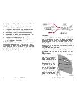
PROPELLER
The propeller (“prop”) converts the engine’s power into thrust to
propel the boat. The right prop for any boat in a specific application
is one that allows the engine to turn up to its full rated RPM, but no
more. It is necessary for the engine to turn to full rated rpm in order to
develop full rated power. If the boat is used for more than one type of
activity, fishing and water skiing for example, the prop can only be
optimized for one situation. Since a spare prop is an excellent safety
item, the purchase of a second propeller which is more efficient for
another application is not
all “added expense”.
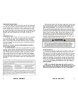
PROPELLER TERMS
Propellers are identi-
fied by two numbers such
as 14 x 17, and a mate-
rial identification, such as
aluminum or stainless steel. The first number is the diameter and the
second is the pitch. The diameter is the distance across the circle
swept by the extreme tips of the propeller blades. The term pitch
comes from the old screw analogy used to approximate propeller ac-
tion. This analogy says that a propeller screws itself through the wa-
ter much as a wood screw works itself into soft pine. The pitch is the
angle of the blades expressed in the theoretical distance a propeller
would travel in each revolution. In the above example the propeller
would advance 17” on each revolution. In reality, the propeller actually
pushes the boat forward less distance than its pitch. The difference
between the pitch and the actual distance traveled is called “slip”.
OUTBOARD PROPULSION SYSTEM
The engine manufacturer supplies all vital information concerning
your engines in the operation and maintenance manuals. Details of
important engine maintenance schedules, lubrication system, cooling
system and engine alert systems are outlined in these manuals. Your
familiarization with this engine reference material will result in the
proper usage and service that is essential for safe and enduring en-
gine performance. These manuals are included with the Owner’s
Packet.