


P:\INST-INS TRUCTIONS\CO NTROL CONSOLES \INST-TCC/RCC REV - 10/20 Page 8
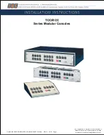
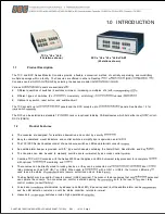
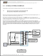
1.0 INTRODUCTION
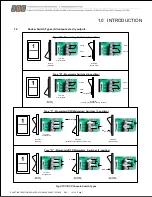
1.5
Switch Panel Configurations
Note(s):
1.
Panel configurations are only available in 4 or 8 switches. All the switches on a panel are the same type (A, B, C or D).
2.
Unless otherwise specified, switches are numbered in sequential order. The first, top-left switch is marked
“1”, and then they
increase sequentially along the top row. If applicable, the sequence continues on the second row.
3.
Switch types A and B are typically best suited for direct release or electrified door locking devices such as Emlocks, Strike s,
Electrified Lockset, etc.
4.
Switch types C and D are suited for devices which have separate inputs for
“open” and “close” functions, such as overhead
doors, rolling gates, etc. These switches do not provide a circuit path when in the
“normal” position.
5.
Full Status monitoring and alarm annunciation requires auxiliary relay auxiliary relay control modules. Consult the factory for
assistance in selecting additional control modules to meet the needs of your specific application
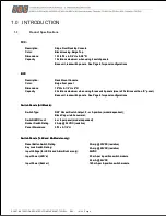
Part No
Description
Image
AL4
Four Momentary Switches with LED's
BL4
Four Maintained Switches with LED's
CL4
Four Momentary/Off/Maintained Switches with LED's
DL4
Four Momentary/Off/Momentary Switches with Leds
AL8-2
Eight Momentary Switches with LED's on 2 panels
BL8-2
Eight Maintained Switches with LED's on 2 panels
CL8-2
Eight Momentary/Off/Maintained Switches with LED's on 2 panels
DL8-2
Eight Momentary/Off/Momentary Switches with LED's on 2 panels
AL8
Eight Momentary Switches with LED's
BL8
Eight Maintained Switches with LED's
CL8
Eight Momentary/Off/Maintained Switches with LED's
DL8
Eight Momentary/Off/Momentary Switches with Led's
AL4E
Four Momentary Switches with LED's, Alarm Shunt, Reset Push
Buttons and Key Lock
BL4E
Four Maintained Switches with LED's, Alarm Shunt, Reset Buttons and
Key Lock
CL4E
Four Momentary/Off/Maintained Switches with LED's, Alarm Shunt,
Reset Buttons and Key Lock
DL4E
Four Momentary/Off/Momentary Switches with LED's, Alarm Shunt,
Reset Buttons and key Lock
EA
Panel with Alarm Shunt, Reset Push Buttons and Key Lock
FA
Blank Panel
CAB7
Black Cabinet for One RCC (7"H x 20-1/2"W x 14-1/2"D
CAB12
Black Cabinet for Dual RCC (12-1/2"H x 20-1/2"W x 14-1/2"D)
(Accomodates two vertically mounted RCC racks; not shown)