


P:\INST-INS TRUCTIONS\CO NTROL CONSOLES \INST-TCC/RCC REV - 10/20 Page 5
1.0 INTRODUCTION
1.1
Product Description
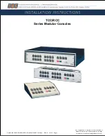
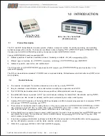
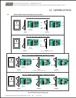
The TCC and RCC Series Modular Consoles provide a flexible, economical method of centrally supervising and
multiple openings within a facility. The Consoles are offered in either a Desktop
or
(RCC)
Consoles can be
by selecting the desired modular
Various
panels are available
•
Different quantities of switches (4 switches minimum, increasing in multiples of 4) with
•
Different types of switches (2 or
momentary or latching),
various
•
Optional key switch, reset button, and audible
The TCC accepts up to
panels and the RCC accepts up to
panels. See Section 1.3 for
switch
The RCC can be installed in a standard
19”
rack or in optional tabletop CAB enclosures which hold either one
or
RCC
’s (CAB12).
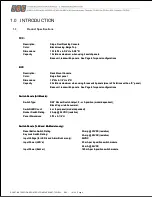
1.2
Product Features
•
The consoles are designed for real-time observation and control by security
•
Easy to understand visual indicators and control switches simplify door supervision and
•
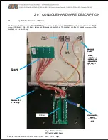
The TCC/RCC Series Consoles consist of an enclosure, switches, LEDs and terminal connector
•
An audible alarm beeper is provided with
“E” type switch panels containing the Alarm Shunt, Reset Button and Key
•
The Consoles can also be used to manually override doors
by an access control
•
Combine TCC or RCC consoles with the Series 600 Power Supplies and UR4-8 universal relay processor for a complete
with optional
monitoring and
•
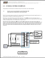
The consoles can be directly wired to locking devices, or they can be connected via
door
relay modules such as SDC UR-1 or UR4-8. When used in
with a UR-1 or UR4-8, the tri-color LEDs may
used to see the status of
doors (secure, authorized unlock, forced
•
The Key Switch may be used for Console Lockout (UR4-8 required). The Lockout feature ensures that only
personnel
can operate the console. Two consoles can control a shared opening by
both to the input of
door relay
control module (consult
•
Forced door
are indicated by a beeper and Red LED
(‘E’ panel required) but the audible alarm can be
and the LED indication remains on until the status condition returns to
•
Heavy duty
switches provide high operational
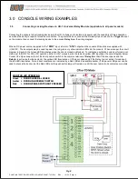
TCC x *L8 x *L4E
(12 stations shown)
RCC x *L8 x *L8 x *L4E x CAB7
(20 stations shown)