

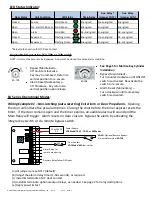


EA Series Board Layout (Back View):
1
Configuration Jumpers – Numbered 1 through 5. By default, all jumpers have been set to OFF. Use the (5)
supplied jumpers, as required. See the table below for a functional description of each jumper.
2
Adjustable Alarm Timer – Determines the amount of time a door can be propped open before an alarm is
activated. Adjustable from 1 to 60 seconds. Turn clockwise to increase time.
3
Input Power Terminals – Requires a 12 or 24VDC +/- 10% power supply (auto-sensing).
4
Control Input Terminals – Dry input used for bypass & alarm reset. Field-selectable as normally open
(default) or normally closed. In a secure state, a held input will bypass the unit. In an alarm state, a
momentary input will reset the alarm providing the door is closed.
This input is factory pre-wired for key switch model EA-728.
5
Door Contact Input – Required for all models. Monitors the open/closed status of the door. Field-
selectable as normally open or normally closed (default).
6
7
Alarm Relay Output – Relay is energized when the unit is powered. An alarm state or loss of power will
de-energize the relay.
PWR (-)
PWR (+)
NO
NO
NC
NC
C
C
1
2
3
4
5
1s
60s
}
}
}
1
2
3
4
5
6
7
*The state of the Main & Aux. relays are
shown when the unit is not powered.
Auxiliary Relay Output – Relay may be configured to follow the DPS input OR to follow a bypass/alarm state.
P:\INSTALLATION INST\Accessories\INST-DOOR PROP.vsd Rev A 07-17 Page 2
Configuration Jumpers
Jumper OFF
Jumper ON
1= Latching Alarm
Disabled (Alarm resets on
door closure)
Enabled. (Requires use of Control Input to reset an alarm OR Jumper #2)
2= Alarm Auto Reset
Disabled
Auto-reset 60 sec. after door closure. (Requires Jumper #1 to be ON)
3= Control Input Polarity Normally Open
Normally Closed
4= DPS Input Polarity
Normally Closed
Normally Open
5= Aux. Relay Function
Follows DPS Input
Follows Bypass/Alarm State