background image

6

A

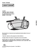
3.1. WIRE CONNECTION

3. SETUP AND FUNCTION SETTING

If the Led display is in normal performing refer to “4.2.1”, you can control the gate by either transmitters or the button 
on the board: “UP”-clockwise moving, “SET”- stop and “DOWN”- Counterclockwise moving.

6

6

7

9

9

6

8

9

6

9

10

11

PB1

PB1, KS1=:

KS1

3

4

FL2

FL2

AC INPUT

1

2

3

4

5

6

7

8

1

2

3

4

5

6

AC INPUT

1

2

3

4

5

6

7

8

9

10

11

1

2

3

4

5

6

AC INPUT

1

2

3

4

5

6

7

8

9

10

11

12

13

14

1

2

3

4

5

6

LED1 Photocells

LED2 Photocells

LED3 RF Learn

ON

ON

OFF

1

2

3

4

5

6

7

8

9

10

11

12

13

14

Close

Stop

GND

Pb

Ph+

Ph2

Ph1

GND

EXT-

EXT+

GND

+13.75

Light

Open

1

2

3

4

5

6

Summary of Contents for INTENSIVE 3A

Page 1: ...utilisation intensive3 24V COULISSANT pour portail Technologie par encodage KIT AUTOMATISME Comfort kit Moteur Cr maill res 2 t l commandes Feu clignotant Moteur Cr maill res 2 t l commandes Feu clign...

Page 2: ...R glages des fonctions programmables 3 5 Essais et v rifications 3 6 R glages SW2 et SW6 4 CARACT RISTIQUES TECHNIQUES 4 1 Caract ristiques techniques 4 2 H2 Photocellule 4 3 TM3 T l commande 4 4 FL2...

Page 3: ...portail motoris la terre pendant la phase de raccordement au r seau lectrique 5 L installation n cessite un personnel qualifi avec des comp tences m caniques et lectriques 6 Placez les commandes autom...

Page 4: ...e c 24Vdc moteur d Batteries de secours option e D verrouillage f Panneau de commande g Terminals 3 2 INSTALLATION 3 4 2 3 e f g a b c d 1 1 24Vdc automatisme coulissant 2 T l commande 3 Photocellule...

Page 5: ...C 2 3 DIMENSION D 2 4 INSTALLATION DU MOTEUR ET DE CR MAILL RE 4 100 25 50 25 1 2m Percez Tracez Maintenez le niveau Pignon moteur...

Page 6: ...uvercle de d verrouillage et d placez le vers la droite Etape 2 Ins rez la cl et tournez dans le sens horaire pour d verrouiller l appareil Etape 3 Tourner la barre dans le sens antihoraire pour d ver...

Page 7: ...ement en sens inverse des aiguilles d une montre 6 6 7 9 9 6 8 9 6 9 10 11 PB1 PB1 KS1 KS1 3 4 FL2 FL2 LED1 Photocellules LED2 Photocellules LED3 RF Apprentissage AC INPUT 1 2 3 4 5 6 7 1 2 3 4 5 6 AC...

Page 8: ...B L affichage de LED Fonctions programmables N L L apprentissage du syst me de l INTENSIVE3 n est pas finalis Erreur pendant la programmation recommencer RUN Le syst me de l INTENSIVE3 est en fonctio...

Page 9: ...secondes Inverser jusqu a la fin Veuillez vous reporter la page 9 le reglement de F3 F3 1 F3 2 F3 3 L ger Lourd L ger Lourd L ger Lourd L ger Lourd L ger Lourd L ger Lourd L ger Lourd L ger Lourd L g...

Page 10: ...vert Aucun effet Aucun effet Ferme le portail Photocellule 1 Photocellule 2 Arr ter l ouverture Ouverture arrete lorsque la finition de d tection recontinue ouvrir Ouverture arrete lorsque la finition...

Page 11: ...GE PI TON OUVERTURE TOTALE D CLENCHEMENT CONTACT SEC EXT ET EXT BORNE 1 ET 2 PASSAGE PI TON PAS UTILIS SW2 Par d faut 1 ON 2 ON 3 ON 4 ON 5 ON 6 ON Dispositif Photocellule 1 Photocellule 2 Stop T l co...

Page 12: ...d entr e Temp rature de fonctionnement Indice de protection Dimensions LxWxH mm Infrarouge 30 m tres 100ms AC DC 12 24V 20 60 IP66 59 x 87 x 38 Application Fr quence Boutons Alimentation Temp rature...

Page 13: ...omfort kit Safety kit Motors Rack 2 remote control Blinker Motors Rack 2 remote control Blinker Photocells intensive3 24V Installation and user manual AUTOMATION KIT EN Encoding system SLIDING for gat...

Page 14: ...5 TESTING AND CHECKING 3 6 SW2 SW6 SETTINGS 4 TECHNICAL CHARACTERIESTICS 4 1 TENICAL DATA SHEET OF BOXER SERIES 4 2 H2 PHOTOCELL DATA SHEET 4 3 TM3 TRANSMITTER DATA SHEET 4 4 FL2 FLASHING LIGHT DATA...

Page 15: ...ors etc being placed properly and away from children 7 For replace or repair of the motorized system only original parts must be applied Any damage caused by inadequate parts and methods will not be c...

Page 16: ...EVICE 1 24Vdc Sliding motor 2 Transmitter 3 safety photo Sensor 4 Flashing light a Operation gear b Limit switch device c 24Vdc motor d Back up batteries e Release device f Control panel g Terminals o...

Page 17: ...C 2 3 DIMENSION OF DEVICE D 2 4 INSTALLATION OF MOTOR GEAR AND GEAR RACK 4 100 25 50 25 1 2m Drill Trace keep the level Motor pinion...

Page 18: ...motor please follow the procedure as below Step1 Push the lid of release chamber and move rightward Step2 Insert the key and turn clockwise to unlock the device Step3 Turn counter clockwise of the bar...

Page 19: ...and DOWN Counterclockwise moving 6 6 7 9 9 6 8 9 6 9 10 11 PB1 PB1 KS1 KS1 3 4 FL2 FL2 AC INPUT 1 2 3 4 5 6 7 8 1 2 3 4 5 6 AC INPUT 1 2 3 4 5 6 7 8 9 10 1 2 3 4 5 6 AC INPUT 1 2 3 4 5 6 7 8 9 10 11 1...

Page 20: ...ompleted C A B A B LED Display Programmable Functions N L The INTENSIVE3 system learning is not done LEA Enter learning mode and then wait for learning instructions ARN The system learning is in progr...

Page 21: ...vy Light Heavy Light Heavy Light Heavy Light Heavy F1 F2 Options of Gate Opening direction Automatic Closing F1 0 F1 1 F2 0 F2 1 F2 2 F2 3 F2 4 F2 5 F2 6 F2 7 F2 8 Clockwise Opening Counterclockwise O...

Page 22: ...atic closing time Reloads automatic closing time Photocell 1 Photocell 2 Stop opening Locks and on release reverses to open Locks and on release continues opening Logic F3 1 The reactions of the photo...

Page 23: ...E RELAY EXT AND EXT DEVICE 1 ET 2 NOT USED PEDESTRIAN ACCESS TOTAL OPENING RELEASE RELAY EXT AND EXT DEVICE 1 ET 2 PEDESTRIAN ACCESS NOT USED SW2 Default 1 ON 2 ON 3 ON 4 ON 5 ON 6 ON Photocell 1 Phot...

Page 24: ...ge Operating Temperature Protection class Dimension Through beam 30 meters 100ms AC DC 12 24V 20 60 IP66 59mm x 87mm x 38mm Application Frequency Coding Buttons Power Supply Operating Temperature Dime...

Page 25: ...50 x RADIOCOMMANDE UNIVERSELLE INTENSIVE 3760074139927 56 80 x PANNEAU SOLAIRE 12 24V 3760074131303 141 10 x montant total produit frais de port TOTAL frais de port paiement par ch que 1 produit 7 12...

Page 26: ......

Page 27: ...VE3B code barre num ro 13 chiffres N lot indiqu dans la zone du code barre du packaging garantie 3 ans N oubliez pas d enregistrer votre garantie dans le mois suivant votre achat Conservez soigneuseme...

Page 28: ...your product product name automation kit for sliding gates INTENSIVE3A INTENSIVE3B gencod 13 numbers batch number close to gencod location warranty 3 years To be send at least 1 month after purchasing...

Page 29: ...pour tout probl me technique veuillez contacter votre installateur ou distributeur...

Reviews: