


KeyPad service manual
Rev.1.1
31
o
Measure with a multimeter the voltage between T2 test point
and GND Jumper (analog ground).
o
If there is a pulse or a steady 5V then the Q3 switch is fine.
The problem is probably the solid-state relay.
o
If there is always 0V and the LED is ON or toggles, then
replace Q3.
Solid State Relay verification
o
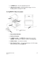
The only way to see if the SSR is behaving accordingly is by
measuring between QD6 and QD5 (see figure 19 for
location). Make sure that there is 120V/230V AC (Toggling
or not). Also refer to figure 19 for an example of what can
be seen on a scope if the control is toggling.
o
Make sure that the heating block temperature is lower than
the target temperature if you want the SSR to toggle.
NOTE: If you’re using a scope, it must be isolated from the wall
outlet.
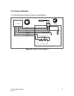
Figure 19:
SSR test pins location
Legend:
1. QD5
2. QD6
1
2


