


Windlass Switch (Optional)
Located in the helm. This switch controls the optional windlass
which is mounted to the deck directly above the rope locker. It
is protected by a circuit breaker of the type and rating recom-
mended by the windlass manufacturer that is located near the
battery switches.
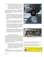
Engine Trim and Tilt Switches
Located in the helm. These switches may be installed in the
engine control handle or on the helm console, depending on
the engines or controls installed in your boat. They control
the trimming and tilting of the engines. Please refer to the
Helm Control Systems chapter and the engine owner’s manual
for information regarding the proper use of the tilt and trim
switches.
Spreader Lights
Located in the switch panel on the optional hardtop. There are
2 switches. One switch activates the aft spreader light and one
switch activates the forward spreader light. The circuit breakers
that protect the spreader light circuits are located on the switch
panel next to the switches.
Hardtop Courtesy Light
Located on the switch panel with the spreader light switches.
Activates the overhead courtesy lights in the optional hardtop.
The circuit breaker that protects the courtesy light circuit is
located on the switch panel next to the switch.
Map Light
Located on the switch panel with the spreader light switches.
Activates the map light in the optional hardtop. The circuit
breaker that protects the map light circuit is located on the
switch panel next to the switch.
Cabin DC Accessory Breaker Panel
Power is distributed to most of the 12-volt accessories in the
cabin through individual circuit breakers located in the cabin
DC breaker panel. A main circuit breaker located in the panel
protects the system from an overload. Some 12-volt accessories
are operated directly by the circuit breaker in the panel. Switch-
es fed by the panel breakers activate other accessories.
A red, low DC voltage light is located in the panel to monitor
the voltage level in the batteries. It will glow red if the house
battery becomes discharged and requires charging.
PROPER FUSE OR BREAKER PROTEC TION MUST
B E P R O V I D E D F O R A L L 12- V O LT E Q U I PM E N T
ADDED. DO NOT OVERLOAD THE ACCESSORY
C I R C U I T B R E A K E R S O R O T H E R C I R C U I T R Y
THROUGH ADDITIONAL 12-VOLT EQUIPMENT.
The following are descriptions of the accessories controlled
by the cabin DC breaker panel:
Shore Main 30 Amps
Supplies the 12-volt current to the DC accessory breakers and
protects the panel from an overload.
Radio
Supplies 12-volt electrical current to the stereo.
Cabin Lights
Supplies 12-volt electrical current to the cabin light switches.
Refrigerator
Supplies 12-volt electrical current directly to the refrigerator
when AC current is not being used.
Water System
Supplies 12-volt electrical current directly to the freshwater
pump pressure switch located on the pump. The pressure
switch automatically controls the water pump when the system
is activated and properly primed.
Vacuum Tank
Supplies electrical current directly to the vacuum pump for the
head if the electric head option is installed in your boat.
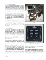
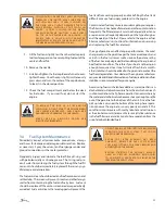
Battery Switch Panel Circuit Breakers
Power is distributed to the helm switch panel through a “push
to reset” helm main circuit breaker located in the battery
switch breaker panel located on the port side wall next to
the helm seat. Other main breakers in the panel protect the
circuits for the windlass and trim tabs. These circuits are
deactivated when the house battery switch is off. Some 12-
volt accessories are operated directly by circuit breakers in
the panel while others are operated by switches fed by the
panel breakers. Each breaker is labeled for the accessory it
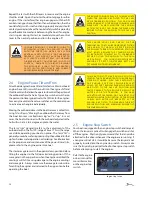
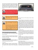
Optional Hardtop Switch Panel
Battery Switch and Breaker Panel
Summary of Contents for 262 Abaco
Page 1: ... Owner s Manual 262 Abaco Scout Boats Inc 2531 Hwy 78 West Summerville SC 29483 ...
Page 2: ... THIS PAGE WAS LEFT BLANK INTENTIONALLY Print Date 6 2007 Current ...
Page 4: ... THIS PAGE WAS LEFT BLANK INTENTIONALLY ...
Page 6: ... THIS PAGE WAS LEFT BLANK INTENTIONALLY ...
Page 10: ...10 THIS PAGE WAS LEFT BLANK INTENTIONALLY ...
Page 30: ...30 THIS PAGE WAS LEFT BLANK INTENTIONALLY ...
Page 40: ...40 THIS PAGE WAS LEFT BLANK INTENTIONALLY ...
Page 46: ...46 THIS PAGE WAS LEFT BLANK INTENTIONALLY ...
Page 52: ...52 THIS PAGE WAS LEFT BLANK INTENTIONALLY ...
Page 64: ...64 THIS PAGE WAS LEFT BLANK INTENTIONALLY ...
Page 70: ...70 THIS PAGE WAS LEFT BLANK INTENTIONALLY ...
Page 91: ...91 Appendix A SCHEMATICS Main Harness ...
Page 92: ...92 Battery Select Panel ...
Page 93: ...93 Battery Select Panel Wiring ...
Page 104: ...104 Appendix C MAINTENANCE SCHEDULE AND LOG ...
Page 105: ...105 MAINTENANCE LOG Hours Date Dealer Service Repairs ...
Page 106: ...106 MAINTENANCE LOG Hours Date Dealer Service Repairs ...
Page 107: ...107 MAINTENANCE LOG Hours Date Dealer Service Repairs ...
Page 108: ...108 MAINTENANCE LOG Hours Date Dealer Service Repairs ...
Page 109: ...109 MAINTENANCE LOG Hours Date Dealer Service Repairs ...
Page 113: ...113 THIS PAGE WAS LEFT BLANK INTEN TIONALLY ...
Page 119: ...119 ...
Page 120: ...120 Scout Boats Inc 2531 Hwy 78 West Summerville SC 29483 ...